Shield electric pump

A technology of shielded electric pumps and shielded motors, applied to pumps, pump devices, pump components, etc., can solve the problems of wasting pipeline materials, inconvenient installation, energy waste, etc., to avoid waste, occupy less space, and improve transmission efficiency Effect

Inactive Publication Date: 2016-09-28
HEFEI XINHU CANNED MOTOR PUMP
View PDF6 Cites 1 Cited by
  • Summary
  • Abstract
  • Description
  • Claims
  • Application Information

AI Technical Summary

Problems solved by technology

[0002] In order to cool the motor and lubricate the bearings, ordinary canned electric pumps must draw a part of the circulating fluid from the mainstream liquid discharged from the impeller into the motor for separate circulation, resulting in a waste of energy
In addition, due to the characteristics of the centrifugal impeller, the liquid flow needs to be sucked axially and discharged radially, which changes the flow direction and cannot be consistent with the pipeline direction, which is not easy to install and wastes pipeline materials. When there is gas or liquid vaporization, it needs to In addition, set the exhaust device, otherwise the pump will be damaged

Method used


Image

  • Shield electric pump

Examples


Embodiment 1

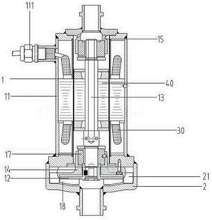
[0017] Such as figure 1 A canned electric pump shown includes a canned motor 1 and a pump body 2, and the pump body 2 is fixedly connected to the canned motor 1;

[0018] The pump body 2 is provided with a pump chamber 21;

[0019] The shielded motor 1 includes a motor casing 11, an impeller 12 and a rotating shaft 13, a front bearing seat 14 and a rear bearing seat 15 are arranged in the motor casing 11, and bearings are respectively arranged in the front bearing seat 14 and the rear bearing seat 15. 17. Both ends of the rotating shaft 13 are respectively connected with the bearings 17 in the front bearing housing 14 and the rear bearing housing 15, the impeller 12 is located in the pump cavity 21 and is fixedly connected with the rotating shaft 13, the impeller Guide vanes 18 are arranged on the outer side of 12, and the guide vanes 18 are connected to the rotating shaft 13. The motor housing 11 is provided with a stator assembly 30 and a rotor assembly 40 in sequence from ...


PUM


Abstract

The invention belongs to the technical field of pump bodies and particularly relates to a shield electric pump. The shield electric pump comprises a shield motor and a pump body. The pump body is fixedly connected to the shield motor. The shield motor comprises a motor shell, an impeller and a rotating shaft. A front bearing block and a rear bearing block are arranged in the motor shell. A shaft sleeve and a bearing are arranged in each of the front bearing block and the rear bearing block. The two ends of the rotating shaft are connected with the bearing in the front bearing block and the bearing in the rear bearing block correspondingly. The impeller is located in the pump cavity and fixedly connected with the rotating shaft. The shield electric pump has the beneficial effects that the conveying efficiency is improved by removing independent circulating liquid, and waste is avoided; the direction of a liquid outlet is the same with that of the shaft, and the liquid outlet is conveniently installed in a pipeline to become part of the pipeline; and due to the wholly-sealed structure of the shell, the structure can be reliable, guide vanes and the bearing blocks are integrally designed, so that the structure is small and exquisite, and the occupied space is small.

Description

technical field [0001] The invention belongs to the technical field of pump bodies, and in particular relates to a shielded electric pump. Background technique [0002] In order to cool the motor and lubricate the bearings, ordinary canned electric pumps must draw a part of the circulating fluid from the mainstream liquid discharged from the impeller into the motor for separate circulation, resulting in a waste of energy. In addition, due to the characteristics of the centrifugal impeller, the liquid flow needs to be sucked axially and discharged radially, which changes the flow direction and cannot be consistent with the pipeline direction, which is not easy to install and wastes pipeline materials. When there is gas or liquid vaporization, it needs to Also set the exhaust device, otherwise the pump will be damaged. Axial flow impellers can achieve axial suction and discharge, but due to their limited use, they cannot replace centrifugal impellers. Centrifugal impellers ar...

Claims


Application Information

Patent Timeline
IPC IPC(8): F04D13/06F04D7/02F04D29/58H02K5/20
CPCF04D7/02F04D13/0606F04D29/5806H02K5/20
Inventor 韩元平
Owner HEFEI XINHU CANNED MOTOR PUMP
Why Eureka
Try Eureka