Double-side bayonet wire duct

A bayonet and wire groove technology, applied in the field of bilateral bayonet wire grooves, can solve the problems of increasing the fixing time and affecting the fixing effect, and achieve the effect of simple structure and convenient fixing.

Inactive Publication Date: 2016-09-28
安徽省挺辉钢管有限公司
View PDF2 Cites 1 Cited by
  • Summary
  • Abstract
  • Description
  • Claims
  • Application Information

AI Technical Summary

Problems solved by technology

[0003] But the trunking on the market is generally divided into two parts: U-shaped groove and cover, and cover is fixed on the U-shaped groove with screw, and there is defect in such fixing mode: when one end is fixed, the other end is movable, Affected stationary effects and increased stationary time

Method used


Image

  • Double-side bayonet wire duct

Examples


Embodiment Construction

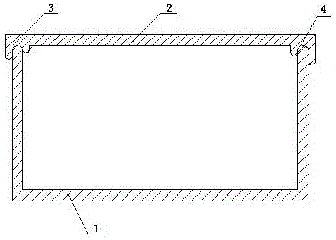
[0008] refer to figure 1 , a double-sided bayonet slot, which includes a U-shaped slot 1, a cover 2, a first bayonet 3 and a second bayonet 4, the first bayonet 3 is located at the left end of the cover, and the second bayonet 4 is located at the right end of the cover , the cover 2 is installed on the U-shaped groove 1 through the first bayonet 3 and the second bayonet 4 .

[0009] The usage method of the present invention: After putting the line body to be arranged into the U-shaped groove, align the position with the bayonet of the cover and push it into the U-shaped groove for fixing.

[0010] To sum up, if there is any change in the structure of the application, as long as it conforms to the principle of the application, it also belongs to the protection scope of the application.


PUM


Abstract

A double-sided bayonet slot relates to the technical field of electrical wiring. It is characterized in that it includes a U-shaped groove, a cover, a first bayonet and a second bayonet, the first bayonet is set at the left end of the cover, the second bayonet is set at the right end of the cover, and the cover passes through the first bayonet and the second bayonet Installed on a U-shaped groove. The invention has the characteristics of simple structure, convenient fixing, time saving and labor saving.

Description

technical field [0001] The invention relates to the technical field of electrical wiring, in particular to a double-sided bayonet slot. Background technique [0002] The trunking is mainly used for the internal wiring of electrical equipment. In the electrical equipment of 1200V and below, it plays the role of mechanical protection and electrical protection for the wires laid therein. After using the product, the wiring is convenient, the wiring is neat, the installation is reliable, and it is easy to find, maintain and Switch lines. [0003] But the trunking on the market is generally divided into two parts: U-shaped groove and cover, and cover is fixed on the U-shaped groove with screw, and there is defect in such fixing mode: when one end is fixed, the other end is movable, Affected the hold effect and increased hold time. Contents of the invention [0004] The purpose of the present invention is to provide a double-sided bayonet slot, which has the characteristics of...

Claims


Application Information

Patent Timeline
Patent Type & Authority Applications(China)
IPC IPC(8): H05K7/02
CPCH05K7/02
Inventor 王林挺
Owner 安徽省挺辉钢管有限公司
Why Eureka
Try Eureka