Supercharge Your Innovation With Domain-Expert AI Agents!

Centrifugal cleaning device and method for operating the centrifugal cleaning device

A cleaning equipment and matching technology, applied in cleaning methods and utensils, chemical instruments and methods, centrifuges, etc., can solve problems such as difficult realization and inflexibility of centrifugal cleaning equipment, and achieve short cycle time, simple operation process, and compact The effect of the design structure

Inactive Publication Date: 2019-04-16
TMS TURNKEY MFG SOLUTIONS
View PDF13 Cites 0 Cited by
  • Summary
  • Abstract
  • Description
  • Claims
  • Application Information

AI Technical Summary

Problems solved by technology

Therefore, such a centrifugal cleaning device is very inflexible, in particular component replacement is only possible with difficulty

Method used


Image

  • Centrifugal cleaning device and method for operating the centrifugal cleaning device
  • Centrifugal cleaning device and method for operating the centrifugal cleaning device
  • Centrifugal cleaning device and method for operating the centrifugal cleaning device

Examples


Embodiment Construction

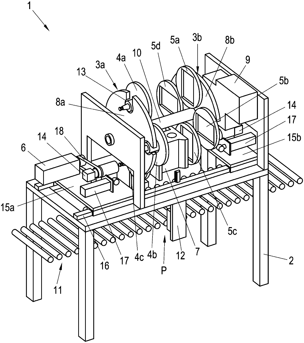
[0026] Below, refer to figure 1 . The centrifugal cleaning device 1 according to the invention is explained in more detail with the aid of a specific advantageous embodiment (in a particularly compact design). The centrifugal cleaning device 1 here comprises a stationary support structure 2 , on which are arranged opposing component receiver magazines 3 a , 3 b and a drive system 6 for the component receiver 4 . There are component receptacles 4a, 4b, 5a-5d held therein. Furthermore, the centrifugal cleaning device 1 comprises opposite clamping means 14 , by means of which the component holders 4 a , 4 b , 5 a - 5 d can be captured, clamped and held. In the exemplary embodiment shown, the component 7 is to be held between two opposing, matching component receptacles 4c, 5c, as will be explained in more detail below. Thus, in figure 1 There are also two component receptacle magazines 3a, 3b arranged axially spaced apart from each other. However, it goes without saying that ...


PUM


Abstract

In order to adapt the centrifugal cleaning device to different components in a simple manner, a clamping unit for clamping and holding a component receiver for the component is provided in the centrifugal cleaning device (1), wherein the clamping unit and the drive system (6) It is releasably connected with the component receiver, and the component receiver is matched with the determined component through the positioning mechanism and / or counterweight arranged thereon, and the clamping unit is arranged on the movable slide seat, The clamping unit can move back and forth between the centrifugal position, the clamping position and the replacement position through the movement of the sliding seat, the clamping position is arranged between the replacement position and the centrifugal position, and the clamping unit is in the clamping position The component receiver is engaged with the component receiver, and the component receiver is located in the receiving part. Each component receiver is matched with a certain component through a positioning mechanism and / or a counterweight, and the clamping unit is connected with the component receiver library in the component receiver. The receptacles of the component receptacle are arranged aligned relative to each other.

Description

technical field [0001] The invention relates to a centrifugal cleaning device with a component receiver and a drive system interacting with the component receiver, which can be connected to an industrially produced component to be centrifuged, the drive system Used to rotate the component receiver. Furthermore, the invention relates to a method for operating a centrifugal cleaning device for centrifuging industrially produced components, in which method the component is conveyed into the centrifugal cleaning device, the component is held by means of a component receiver, driven The system rotates the component receiver to centrifuge the retained component, and after centrifugation, loosens the component receiver from the component and removes the centrifuged component from the centrifugal cleaning apparatus. The invention also relates to a component receiver for such a centrifugal cleaning device. Background technique [0002] Industrially produced components (such as engi...

Claims


Application Information

Patent Timeline
Patent Type & Authority Patents(China)
IPC IPC(8): B08B7/02F26B5/08
CPCB08B7/00F26B5/08B04B5/00F26B19/00F26B25/02B08B7/02F26B15/02B08B13/00B23Q11/0075
Inventor S·维尔登
Owner TMS TURNKEY MFG SOLUTIONS
Features
  • R&D
  • Intellectual Property
  • Life Sciences
  • Materials
  • Tech Scout
  • Unparalleled Data Quality
  • Higher Quality Content
  • 60% Fewer Hallucinations
Learn More