Method for recognizing engineering sweet spots in shale stratum

A shale and formation technology, applied in the field of identifying engineering sweet spots of gas-bearing shale formations, can solve problems such as describing and defining engineering sweet spots, and achieve the effect of improving development efficiency

Active Publication Date: 2016-10-05
CHINA PETROLEUM & CHEM CORP +1
View PDF4 Cites 19 Cited by
  • Summary
  • Abstract
  • Description
  • Claims
  • Application Information

AI Technical Summary

Problems solved by technology

However, there are not yet plausible parameters to describe and define engineering sweet spots

Method used


Image

  • Method for recognizing engineering sweet spots in shale stratum
  • Method for recognizing engineering sweet spots in shale stratum
  • Method for recognizing engineering sweet spots in shale stratum

Examples


Embodiment 1

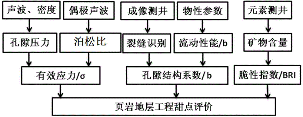
[0060] In this example, the technical ideas for identifying engineering sweet spots in shale formations are as follows: figure 1 As shown, firstly, the pore pressure is calculated according to the acoustic wave and density logging methods, the Poisson’s ratio is calculated by dipole acoustic logging, and the maximum horizontal effective stress of the formation is calculated according to the two values; the experimental data of porosity and permeability can be used to calculate Formation pore structure index; the brittle mineral content is used to calculate the formation brittleness index, and these three parameters are used to determine the shale formation engineering sweet spot coefficient.

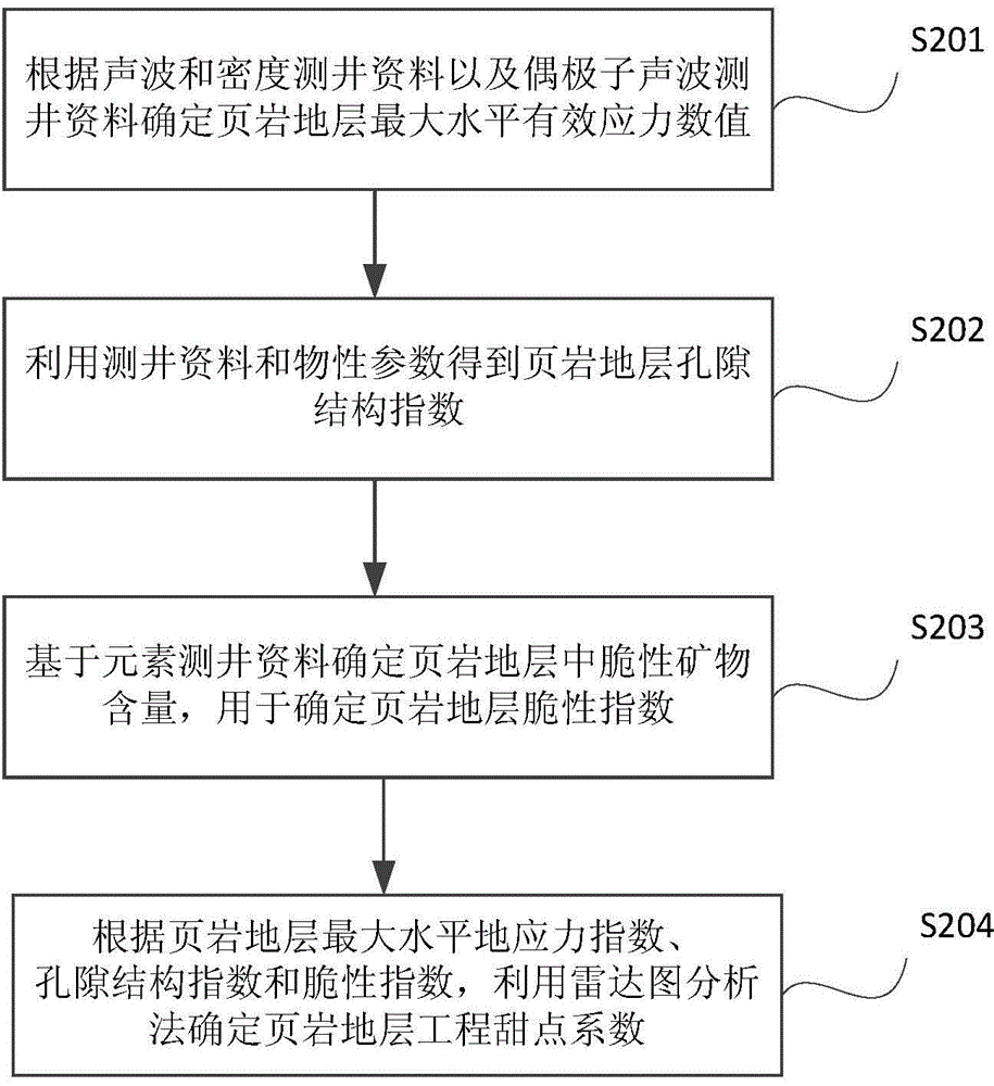
[0061] figure 2 is a flow chart of the steps of the method for identifying engineering sweet spots in shale formations according to this embodiment. The following combination figure 2 The identification method provided in this embodiment will be described in detail.

[0062] In step...

Embodiment 2

[0096]In this embodiment, the logging data of a well in a shale formation in a block in southwest China is used as an example to illustrate the identification results of engineering sweet spots in shale formations.

[0097] The lithology of high-quality shale in this block is mainly composed of yellow-gray shale and silty shale interbedded with thin lenticular limestone. is 40MPa, and the average pore structure index of shale formation is 4.

[0098] The extreme values ​​and intervals of engineering sweet spot parameters in this area are as follows: the maximum brittleness index is 80%, the maximum horizontal effective stress interval is 30-45MPa, and the maximum pore structure index is 6. The method of drawing a radar chart after normalizing engineering sweet spot parameters can identify whether the well engineering sweet spot is good or bad.

[0099] Among them, the brittleness index after normalization is BRI=0.7 / 0.8=0.875, and the maximum horizontal effective stress after...


PUM


Abstract

The invention discloses a method for recognizing engineering sweet spots in a shale stratum. The method includes the following steps that the maximum horizontal effective stress value of the shale stratum is determined according to sound wave and density logging information and dipole sound wave logging information; the pore structure index of the shale stratum is obtained according to imaging logging information and physical parameters; the brittle mineral content in the shale stratum is determined based on element logging information and is used for determining the brittleness index of the shale stratum; and according to the maximum horizontal effective stress value, the pore structure index and the brittleness index of the shale stratum, the engineering sweet spot coefficient of the shale stratum is determined through a radar map analyzing method, and the engineering sweet spot coefficient is used for recognizing the engineering sweet spots in the shale stratum. By analyzing the engineering sweet spot coefficient of the shale stratum, it is determined that the brittleness index, the maximum horizontal effective stress value and the pore structure index are the main parameters of the engineering sweet spots in the shale stratum, and the engineering sweet spots in the shale stratum can be accurately recognized according to the existing logging information.

Description

technical field [0001] The invention relates to the technical field of geological exploration, in particular to a method for identifying engineering sweet spots in gas-bearing shale formations. Background technique [0002] The sweet spot in the shale formation refers to the part of the formation that has good reservoir geological quality and is relatively easy to perform fracturing engineering. The sweet spot is very important to the development of shale formations. Finding the sweet spot is conducive to reducing the cost of shale exploration and development and increasing the productivity of gas-bearing shale formations. [0003] The term "sweet spot" first appeared in relation to difficult-to-develop reservoirs, and refers to a small fault block in conventional oil and gas layers with good reservoir quality, which was subsequently used in coalbed methane. The sweet spots in coalbed methane are high-potential gas-producing areas, with better natural fractures and coal sea...

Claims


Application Information

Patent Timeline
Patent Type & Authority Applications(China)
IPC IPC(8): E21B49/00
Inventor 廖东良曾义金陆黄生
Owner CHINA PETROLEUM & CHEM CORP
Why Eureka
Try Eureka