Jig for linear probes

A probe and line-type technology, applied in the field of fixtures for line-type probes, can solve the problems that line-type probes cannot touch, line-type probes cannot slide, etc., and achieve the effect of restraining movement

Active Publication Date: 2016-10-05
ORGAN NEEDLE CO LTD
View PDF12 Cites 5 Cited by
  • Summary
  • Abstract
  • Description
  • Claims
  • Application Information

AI Technical Summary

Problems solved by technology

When the sliding resistance increases due to wear, there is a problem that the linear probe cannot slide smoothly in the through-hole 20 on the rear end side, and the tip of the linear probe cannot contact the contact terminal of the electrode substrate.

Method used


Image

  • Jig for linear probes
  • Jig for linear probes
  • Jig for linear probes

Examples


Embodiment Construction

[0032] Embodiments of the present invention will be described with reference to the drawings.

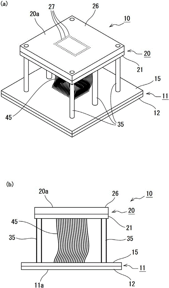
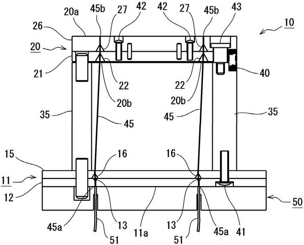
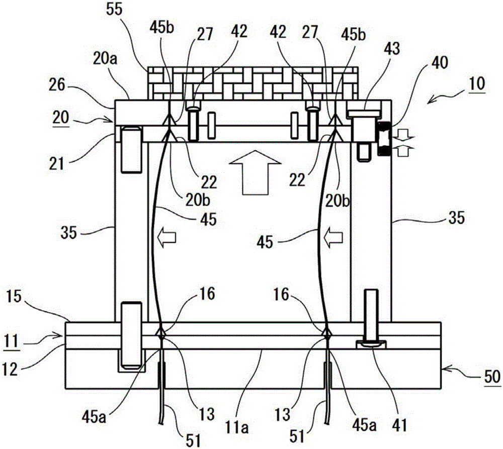
[0033] The wire probe jig 10 of the present embodiment is a member for holding the wire probe 45 used for substrate inspection, and is arranged between the inspection target substrate 55 and the electrode substrate 50 . Such as figure 1 As shown, the jig 10 for a wire probe holds a plurality of wire probes 45 so that the wire probes 45 do not come into contact with each other. When using the jig 10 for a linear probe, the other side of the jig 10 for a linear probe is fixed to the surface of the electrode substrate 50 with one surface of the jig 10 for a linear probe fixed. The surface is pressed against a substrate 55 to be inspected such as a semiconductor integrated circuit, so that both ends of the held wire probe 45 come into contact with the terminals of the electrode substrate 50 and the substrate 55 to be inspected, respectively.

[0034] Such as figure 2 As shown in FI...


PUM


Abstract

The invention provides a jig for linear probes, which enables two terminals of the linear probe to be in reliable contact with a terminal of an electrode substrate and a terminal of a detected substrate without producing wearing of the linear probe. A base part (11) and a top part (20) are configured in a manner of relative movement; the base part (11) maintains the rear end (45a) of the linear probe (45) and ensures the contact between the rear end part (45) and an electrode substrate (50), and the top part (20) enables a front end part (45b) to be in contact with a substrate to be detected (55); the base part (11) comprises a first bottom plate (12) and a second bottom plate (15); the first bottom plate (12) is provided with a first guiding hole (13) for the linear probe (45) to pass through; the second bottom plate (15) is provided with a second guiding hole (16) which is arranged in a manner of staggering in a predetermined direction with the center of the second guiding hole (16) opposite to the center of the first guiding hole (13).

Description

technical field [0001] The present invention relates to a jig for a line probe used in substrate inspection, which is arranged between an electrode substrate and a substrate to be inspected. Background technique [0002] Conventionally, in the conduction inspection and electrical characteristic inspection of semiconductor integrated circuits and the like (substrates to be inspected), inspections using ultra-thin wire probes have been performed. For example, a method is known in which a plurality of wire probes are held by a jig for wire probes, the jig for wire probes is sandwiched between an electrode substrate and a substrate to be inspected, and the two sides of the wire probes are The inspection is carried out by contacting the terminal of the electrode substrate and the terminal of the substrate to be inspected respectively. [0003] In such an inspection method, various methods have been proposed in order to reliably bring both ends of the wire probe into contact with...

Claims


Application Information

Patent Timeline
Patent Type & Authority Applications(China)
IPC IPC(8): G01R1/073
CPCG01R1/06716G01R1/073
Inventor 加藤靖典大西正树
Owner ORGAN NEEDLE CO LTD
Why Eureka
Try Eureka