Multipole switch formed from multiple pole housings

A switch and housing technology, applied in the field of multi-pole switches

Active Publication Date: 2016-10-05
SIEMENS AG
View PDF9 Cites 2 Cited by
  • Summary
  • Abstract
  • Description
  • Claims
  • Application Information

AI Technical Summary

Problems solved by technology

[0004] Here, by opening some openings the quest

Method used


Image

  • Multipole switch formed from multiple pole housings
  • Multipole switch formed from multiple pole housings

Examples


Embodiment Construction

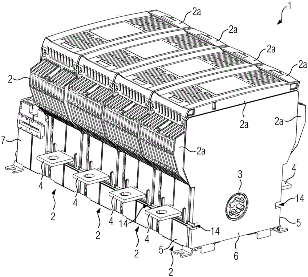
[0016] figure 1 A switch 1 is shown which has four pole housings 2 (four-pole switch). The pole housings 2 are arranged laterally side by side, wherein the inner side walls 10 abut one another. The switching shaft 3 extends transversely through the pole housing 2 and opens and closes switching contacts (not shown) arranged in the pole housing 2 , respectively, depending on the direction of rotation. Two (first) terminal elements 4 in the form of terminal lugs extend outwards through the pole housing 2 on mutually opposite (first) sides 5 transverse to the switching axis 3 .

[0017] Instead of the side wall 10 , a cover plate 6 is provided on the outer side, which extends parallel to the side wall 10 of the pole housing 2 .

[0018] For actuating the switch shaft 3 , a control device 7 is provided on the opposite (outer) side of the switch 1 .

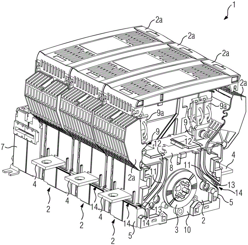
[0019] figure 2 shows the button to remove the pole housing 2 figure 1 switch 1, so the pole housing 2 at the front is visible....


PUM


Abstract

The invention relates to a multi-pole switch (1) with a plurality of pole housings (2) lying laterally against each other, the switch having a switching shaft (3) for a separate arrangement in the pole housing (2) switch contacts; two first terminal elements (4), which are respectively guided outwards through the pole housing (2) on two opposite first sides (5); two second terminal elements ( 9 ), which are each guided outwards through the pole housing ( 2 ) on one of the two opposite second sides ( 8 ) and make contact there with the contacts of the electrical fuse. In order to realize the retrofitting of the wires in order to monitor the fuses and thereby prevent contact with live parts and maintain the necessary dielectric distance, it is proposed to arrange on the side walls (10) of each pole housing (2) two ends (12 , 13) an open wire channel (11), wherein one end (12) leads into the area of ​​the terminal element (9), and the other end (13) is connected to one of the two first sides (5) The wires that meet and can be connected to the contacts of the fuse can be guided outwards through the wire channel (11).

Description

technical field [0001] The invention relates to a multi-pole switch comprising a plurality of pole housings which are arranged laterally side by side with mutually abutting side walls, the switch having a switching shaft which extends transversely through the through the pole housings and for separating the switch contacts arranged in these pole housings for opening the switch; the switch also has two first terminal elements which are respectively transverse to the switch axis is guided outwards through the pole housing on two opposite first sides; the switch also has two second terminal elements which are each transverse As the switching shaft is guided outwards through the pole housing, it contacts contacts of an electrical fuse which is located below a cap-shaped, electrically insulating cover. Background technique [0002] Multipole switches are known in particular as load disconnectors and consist of a plurality of pole housings which are arranged next to each other, w...

Claims


Application Information

Patent Timeline
IPC IPC(8): H01H9/10
CPCH01H71/0214H01H9/106H01H71/1027H01H2071/1036
Inventor F.内斯
Owner SIEMENS AG
Why Eureka
Try Eureka