A multi-head high-power DC charging pile system

A DC charging pile, high-power technology, applied in current collectors, electric energy management, electric vehicles, etc., can solve the problem of not being able to charge multiple vehicles at the same time, and achieve the effects of strong versatility, cost saving, and space saving

Active Publication Date: 2018-09-25
肖伟
View PDF6 Cites 0 Cited by
  • Summary
  • Abstract
  • Description
  • Claims
  • Application Information

AI Technical Summary

Problems solved by technology

[0004] The technical problem to be solved by the present invention is to provide a multi-gun head high-power DC charging pile system to solve the problem that the current charging piles cannot simultaneously charge multiple vehicles of different voltage levels at the same time

Method used


Image

  • A multi-head high-power DC charging pile system
  • A multi-head high-power DC charging pile system
  • A multi-head high-power DC charging pile system

Examples


Embodiment 1

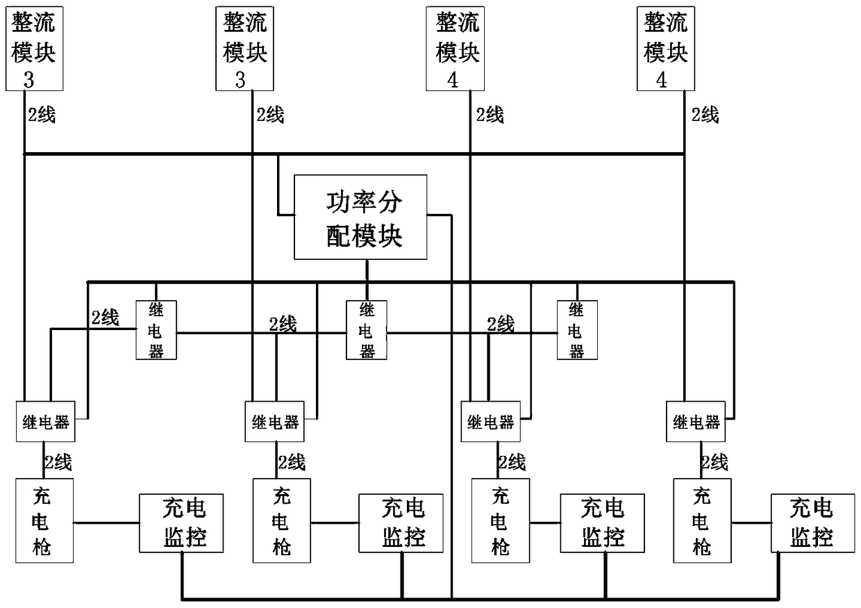
[0026] The technical problem to be solved by the present invention is to provide a multi-tip high-power DC charging pile system, which can perfectly solve the problem that a DC charging pile system with multiple charging gun heads can simultaneously charge different vehicles with different voltage levels. Topology problem. The core idea is to connect (fix) multiple rectifier modules inside the charging pile system in groups, and then let the grouped rectifier module groups freely connect and combine with each other, and then connect with different charging gun heads to form several charging stations with different power. One charging gun, so it can charge different electric vehicles at the same time, meet the requirements of various electric vehicles for charging piles, and meet the requirements of a pile of multi-purpose and simultaneous charging.

[0027] A multi-tip high-power DC charging pile system provided in this specific embodiment is as follows: figure 1 and figure...

Embodiment 2

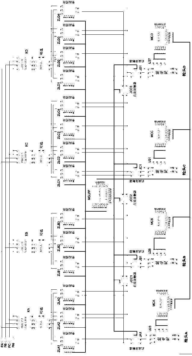
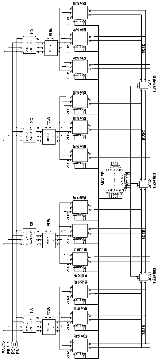
[0039] A multi-tip high-power DC charging pile system provided in this specific embodiment is as follows: Figure 3 to Figure 6 As shown, the difference from Embodiment 1 is that there are 12 rectifier modules in total, and three of them are connected in parallel to form a group. Its output DC busbars are BUSA, BUSB, BUSC, and BUSD, which are respectively connected to charging A gun head, B gun head, C gun head, and D gun head through JA, JB, JC, and JD DC contactors. The communication interface of each module is connected with the power distribution module MGLFP. The DC buses are BUSA, BUSB, BUSC, and BUSD, which are connected through JCC1, JCC2, and JCC3 DC contactors respectively.

[0040] In actual use, if JCC1 is off, JCC2 is off, and JCC3 is off, the DC busbars are separated at this time, and the charging pile becomes four low-power charging guns; JCC1 is closed, JCC2 is off, and JCC3 is closed, and the DC busbars BUSA and BUSB are merged at this time. BUSC and BUSD ar...


PUM


Abstract

The invention discloses a multi-gun-head large power direct current charging pile system. The multi-gun-head large power direct current charging pile system comprises rectification units, charging guns, electric monitoring units and a power distribution module, wherein the number of the charging guns is 2 or more than 2; the number of the rectification units are corresponding to the number of the charging guns; the power distribution module is connected with each rectification unit and each charging gun; each charging gun is connected with the power distribution module through a charging monitoring unit. The multi-gun-head large power direct current charging pile system is not only provided with a plurality of charging guns, but also is provided with the power distribution module, so that free distribution of the charging power for each charging gun is realized. For the multi-gun-head large power direct current charging pile system, the plurality of gun heads can charge multi kinds of vehicles at the same time, such as a large vehicle, a mini-bus and a small vehicle. Practice has proved that the multi-gun-head large power direct current charging pile system has the advantages of being high in practicability, reliability and universality, saving the cost and the space, being high in the utilization rate, and being low in investment.

Description

technical field [0001] The present invention relates to rectification technology, three-level soft-switching DC conversion technology, power distribution technology, digital control technology, charging control technology and other fields in the field of power electronics technology, in particular to a DC charging pile system, especially to a multi-gun The first high-power DC charging pile system. Background technique [0002] At present, the DC charging piles on the market can be divided into low-voltage charging piles and high-voltage charging piles according to the voltage; according to the power, they can be divided into low-power charging piles, medium-power charging piles and high-power charging piles. But no matter what kind of charging pile, it is generally a single pile with a single gun head, which means that it can only charge one car at a time. [0003] Recently, dual-gun charging piles have also appeared, but in fact, only two sets of equipment are installed in...

Claims


Application Information

Patent Timeline
Patent Type & Authority Patents(China)
IPC IPC(8): H02J7/02B60L11/18
CPCY02T10/72
Inventor 刘双锋梅凌陈春贵
Owner 肖伟
Why Eureka
Try Eureka