Substrate transfer apparatus

A technology for transferring devices and substrates, used in transportation and packaging, conveyor objects, electrical components, etc., can solve problems such as vacuum pump failures, and achieve the effect of increasing movement margins

Active Publication Date: 2016-10-05
ULVAC KOREA
View PDF5 Cites 10 Cited by
  • Summary
  • Abstract
  • Description
  • Claims
  • Application Information

AI Technical Summary

Problems solved by technology

Also, the particles are introduced into the vacuum pump used to creat

Method used


Image

  • Substrate transfer apparatus
  • Substrate transfer apparatus
  • Substrate transfer apparatus

Examples


Embodiment Construction

[0040] Hereinafter, exemplary embodiments will be described in more detail with reference to the accompanying drawings. However, this invention may take different forms and should not be construed as limited to the embodiments set forth herein. Rather, these embodiments are provided so that this disclosure will be thorough and complete, and will fully convey the scope of the invention to those skilled in the art.

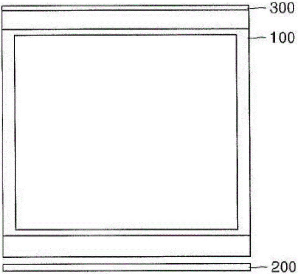
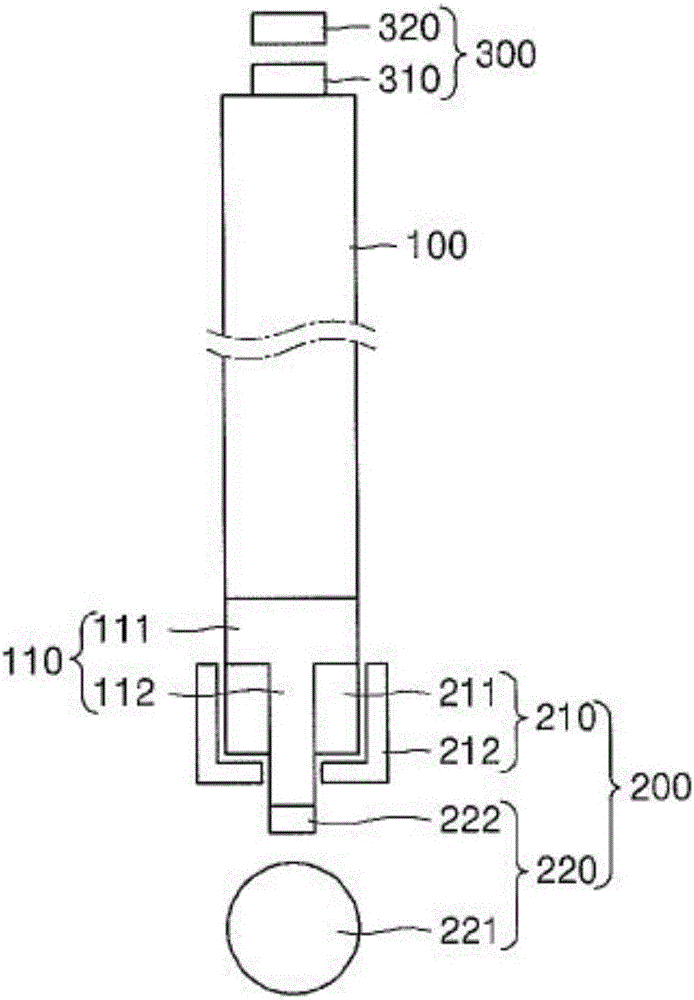
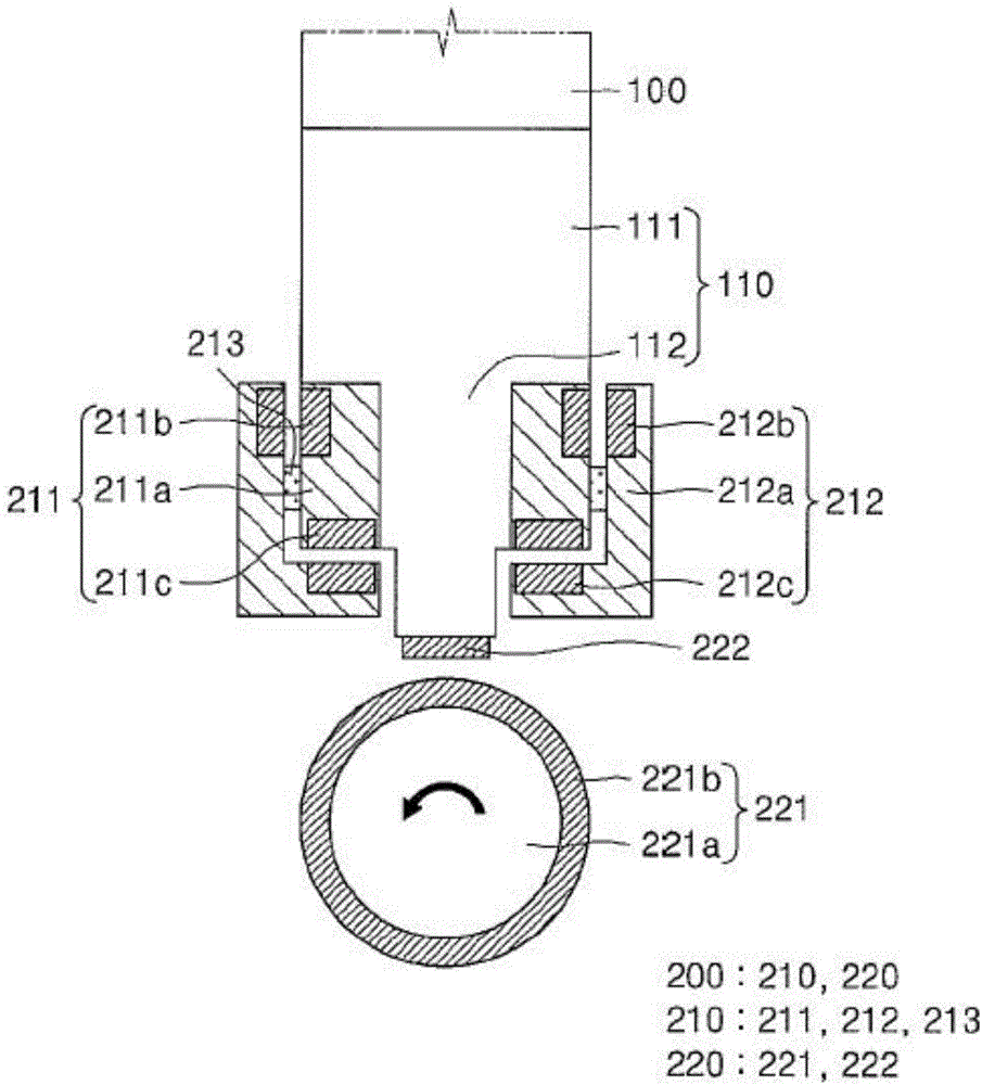
[0041] figure 1 is a front view of the substrate transfer apparatus according to the first exemplary embodiment, and figure 2 is a side view illustrating the substrate transfer apparatus according to the first exemplary embodiment. That is, viewed from the direction of the mounting substrate, figure 1 is the front view, and figure 2 is a side view. again, image 3 is a side view illustrating the magnetic transfer unit of the substrate transfer apparatus according to the first exemplary embodiment, and Figure 4 is a schematic diagram illustrating a magnetic...


PUM


Abstract

The present invention presents a substrate transfer apparatus comprising: a tray on which a substrate is loaded; a magnetic transfer unit provided at a lower side of the tray, magnetically levitating the tray, and transferring the tray by magnetic force; a guide unit for guiding the transfer of the tray by not making contact with the tray; and an interval maintenance means provided at at least one region between the magnetic transfer unit and the guide unit.

Description

technical field [0001] The present invention relates to a substrate transfer device, and more particularly to a substrate transfer device that transfers a tray mounted with a substrate via a contactless method. Background technique [0002] Generally speaking, Flat Panel Display devices (FPD for short) (such as Liquid Crystal Display devices (LCD for short), Plasma Display Panel devices (PDP for short), field emission Field Emission Display device (FED for short) and Electroluminescence Display device (ELD for short) are manufactured by performing multiple processes on a substrate. That is, on the substrate, a deposition process, a photolithography process, and an etching process are repeated multiple times, and cleaning, attaching, and cutting processes are additionally performed to manufacture a flat panel display device. [0003] Such manufacturing processes of flat panel display devices are performed inside a plurality of chambers in which optimal environments are prepa...

Claims


Application Information

Patent Timeline
IPC IPC(8): H01L21/673H01L21/677H01L21/68
CPCH01L21/673H01L21/677H01L21/68H01L2221/67H01L2221/683
Inventor 金正健金善吉金南训金锺大高元一苏秉镐孙承京李起泰李尚浩千敏镐韩应龙
Owner ULVAC KOREA
Why Eureka
Try Eureka