A magnetic gear system and method for reducing transmission of torque pulsation

A magnetic gear and energy storage system technology, applied in control systems, permanent magnetic clutches/brakes, electric components, etc., can solve problems such as complex shaft layout

Inactive Publication Date: 2016-10-05
MAGNOMATICS LTD
View PDF11 Cites 7 Cited by
  • Summary
  • Abstract
  • Description
  • Claims
  • Application Information

AI Technical Summary

Problems solved by technology

[0011] However, this results in a complex shaft arrangement as the innermost gear needs to be accessed within the confines of the coaxial drive shaft

Method used


Image

  • A magnetic gear system and method for reducing transmission of torque pulsation
  • A magnetic gear system and method for reducing transmission of torque pulsation
  • A magnetic gear system and method for reducing transmission of torque pulsation

Examples


Embodiment approach 1

[0177] Embodiment 1: Three-rotor equipment

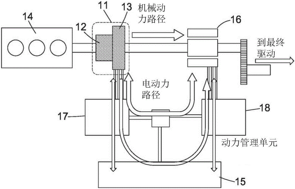
[0178] refer to Figure 7 and Figure 8 , in this embodiment an external control field interacting with the accompanying field generated by the (permanent magnet) PM array attached to the rotor. This rotor is rotated by means of an external device which preferably carries a stator of windings which surround the stator and are concentric with the gear rotor for packaging, as Figure 7 shown. Figure 7 Shown are a motor / generator stator 71 with windings used as control rotors, a motor / generator rotor 72, a magnetically geared outer PM rotor 73, a pole piece rotor (input or output) 74, and a magnetically geared PM rotor 75 (input or output).

[0179] There are many options for this outer control rotor. For example:

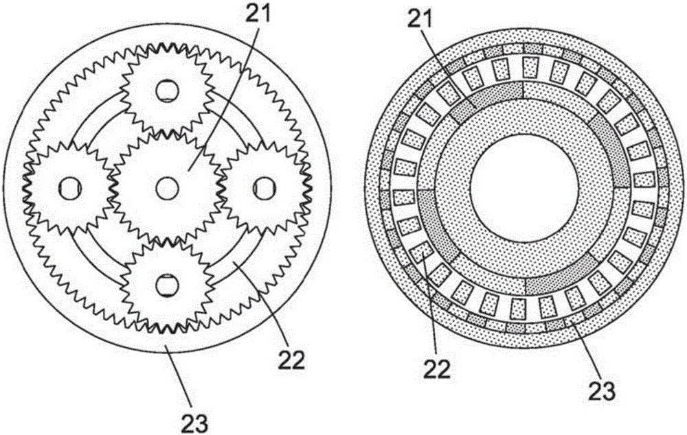
[0180] A. PM inner and outer - each array has a different number of poles than the back iron. This enables independent optimization of gears and motor / generators, as Figure 8 shown.

[0181] B. The PM has the sam...

Embodiment approach 2

[0193] Embodiment 2: two-rotor equipment

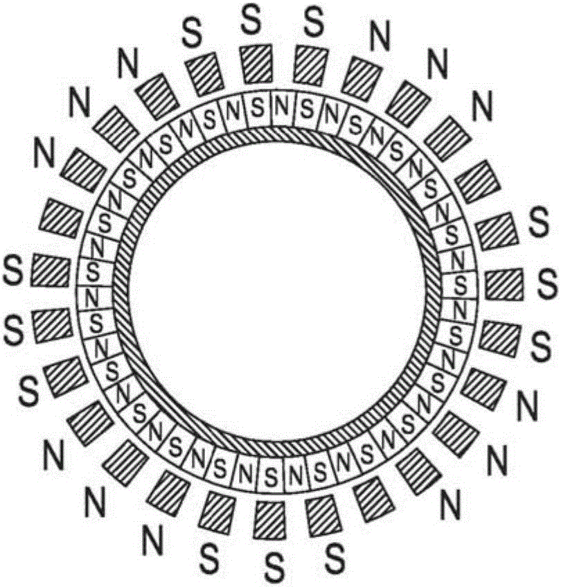
[0194] In this embodiment, the control component is not a physical rotor, but is implemented by coupling the accompanying field with the field controlling the stator. Current power split components consist of an array of permanent magnets (usually the output rotor) and a pole piece modulation array (usually the input rotor). The accompanying field generated by the magnetic field generated by the PM interacting with the pole pieces is coupled with the spatial field generated by a set of windings to generate torque and hence gearing operation as Figure 12 shown. If the current in the winding is fixed, the gear works with a fixed gear ratio. The external field is rotated by supplying a temporally shifted current (typically a three-phase 120-degree shifted current) to a spatially distributed winding (typically a three-phase 120-degree-shifted winding). The gear ratio is then changed as described above.

[0195] One possible way to ex...


PUM


Abstract

A system comprises an input member, an output member, a magnetic gear connecting the input member to the output member and control means arranged to control the flow of power from the input member to the output member. The magnetic gear comprises a first set of magnetic poles, a second set of magnetic poles, and a set of pole pieces arranged to modulate the magnetic field between the first set of magnetic poles and the second set of magnetic poles. The control means comprises means for reducing the transmission of torque pulsation and / or oscillation from the input member to the output member.

Description

technical field [0001] The present disclosure relates to systems and methods in which magnetic gears are arranged and / or controlled to reduce torque ripple from, for example, an internal combustion engine to other components of a vehicle. Background technique [0002] All vehicles require variable road load demands such as speed and torque to match the output of the engine. The engine operating curve has regions of higher and lower efficiency and can give many different combinations of engine torque and speed at a given power level (which is the product of torque and speed) that can give higher or higher Inefficiency and thus higher or lower fuel consumption and emissions. This has historically been accomplished in two ways: with a discrete number of gears that the driver engages manually or automatically through a control mechanism; or with continuously variable transmission (CVT) systems that employ mechanical components such as bevel gear drives. The latter have no fixe...

Claims


Application Information

Patent Timeline
Patent Type & Authority Applications(China)
IPC IPC(8): H02P6/00H02K49/10
CPCH02K49/102H02P6/00H02K7/11H02P6/32H02P17/00
Inventor 斯图尔特·卡尔弗利杰夫·伯查尔
Owner MAGNOMATICS LTD
Why Eureka
Try Eureka