Irrigating aspirator

A suction device and suction tube technology, applied in the field of medical devices, can solve problems such as affecting the progress of the operation and not being able to be sucked away

Inactive Publication Date: 2016-10-12
胡玥
View PDF1 Cites 6 Cited by
  • Summary
  • Abstract
  • Description
  • Claims
  • Application Information

AI Technical Summary

Problems solved by technology

[0002] The patent No. 200920009039.4 of the Chinese invention patent integrated flushing suction device proposes an integrated flushing suction device. There is a certain distance between the suction channel and the flushing channel of the above-mentioned integrated flushing suction device. When suction and flushing are performed at the same time, it cannot be quickly The flushed water will be sucked away through the suction channel, which will affect the progress of the operation

Method used


Image

  • Irrigating aspirator
  • Irrigating aspirator
  • Irrigating aspirator

Examples


Embodiment 1

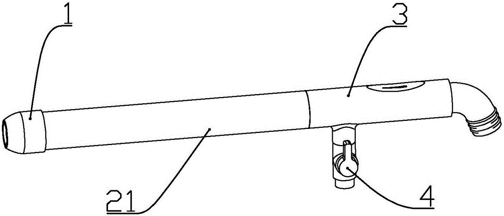
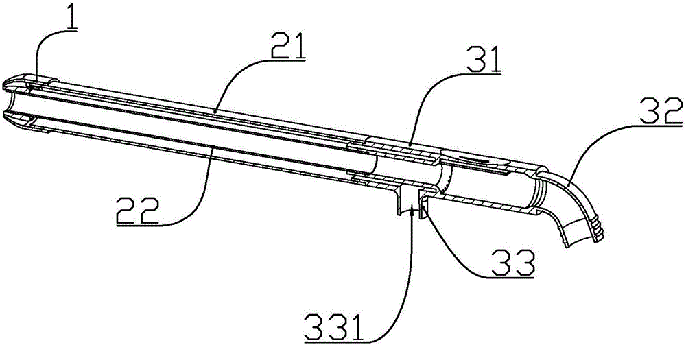
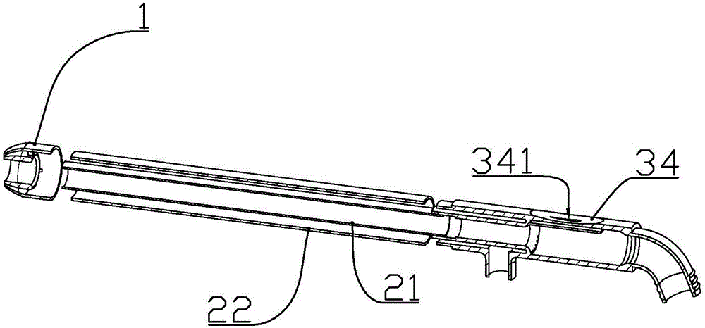
[0025] according to Figure 1 to Figure 6 As shown, a flushing aspirator described in this embodiment includes a nozzle assembly 1, which is inserted into the outer tube 21 and the inner tube 22 at the rear end of the nozzle assembly, and is fixedly connected to the rear end of the outer tube and the inner tube. A handle assembly 3 and a valve 4 fixedly connected to the lower end of the handle assembly; the spray head assembly includes an outer pipe connection sleeve 11 socketed with the outer pipe, and an inner pipe connection sleeve socketed with the inner pipe 12. Three connecting ribs 14 uniformly distributed in the circumferential direction are formed between the outer tube connecting sleeve and the inner tube connecting sleeve; Ring-shaped water spout 13; a suction hole 121 is formed in the middle of the inner pipe connection sleeve; the handle assembly includes a handle body 31, and a negative pressure control part 34 formed at the rear of the handle body is formed on t...

Embodiment 2

[0031]A flushing aspirator described in this embodiment includes a spray head assembly 1, an outer tube 21 and an inner tube 22 inserted at the rear end of the spray head assembly, and a handle assembly 3 fixedly connected to the rear end of the outer tube and the inner tube And the valve 4 fixedly connected to the lower end of the handle assembly; the spray head assembly includes an outer pipe connection sleeve 11 socketed with the outer pipe, and an inner pipe connection sleeve 12 socketed with the inner pipe; the Three connecting ribs 14 uniformly distributed along the circumferential direction are formed between the outer pipe connecting sleeve and the inner pipe connecting sleeve; an annular water spray is formed between the outer pipe connecting sleeve and the front end of the inner pipe connecting sleeve. port 13; a suction hole 121 is formed in the middle of the inner tube connecting sleeve; the handle assembly includes a handle body 31, a negative pressure control part...


PUM


Abstract

The invention discloses an irrigating aspirator. The irrigating aspirator comprises a spray head assembly, an outer pipe, an inner pipe, a handle assembly and a valve, wherein the spray head assembly comprises an outer pipe connecting sleeve and an inner pipe connecting sleeve; an annular water spray opening is formed between the front end part of the outer pipe connecting sleeve and the front end part of the inner pipe connecting sleeve; the handle assembly comprises a handle body and a negative pressure control part; an air inlet is formed in the negative pressure control part; the spray head assembly, the outer pipe and the inner pipe are respectively and integrally formed by adopting plastic; the handle assembly is formed by fixedly connecting a left half body and a right half body which are symmetrical; during use, the air inlet is pressed by using a thumb, an outside negative pressure source is opened, the valve is opened, and then water irrigates a part needing to be irrigated; the front end of the outer connecting sleeve of the spray head assembly is in a conical surface, so that sprayed water can be gathered to a point at the front end of an aspiration hole; the aspiration hole of the spray head assembly is enabled to align to a part needing to be aspirated and irrigated, and then pollutants attached to the surface can be aspirated into the irrigating aspirator from an aspiration opening of a water spraying assembly.

Description

technical field [0001] The invention belongs to the field of medical equipment, and in particular relates to a flushing aspirator. Background technique [0002] The patent No. 200920009039.4 of the Chinese invention patent integrated flushing suction device proposes an integrated flushing suction device. There is a certain distance between the suction channel and the flushing channel of the above-mentioned integrated flushing suction device. When suction and flushing are performed at the same time, it cannot be quickly The flushed water will be sucked away through the suction channel, which will affect the progress of the operation. Contents of the invention [0003] The technical problem to be solved by the present invention is to provide a flushing suction device that can immediately suck up the sprayed water and the dirt that is carried when the suction and flushing are carried out simultaneously. [0004] In order to achieve the purpose of the present invention, the f...

Claims


Application Information

Patent Timeline
Patent Type & Authority Applications(China)
IPC IPC(8): A61M3/02
CPCA61M3/0283
Inventor 胡玥
Owner 胡玥
Why Eureka
Try Eureka