Centrifugal tube facilitating liquid sampling

A centrifuge tube and pipette technology, which is applied in the field of centrifuge tubes and medical instruments, can solve the problems of troublesome steps, disadvantageous work efficiency, improvement and the like, and achieves the effects of not easy pollution, good sealing performance and convenient liquid taking.

Active Publication Date: 2016-10-12
JIANGSU KEHUA MEDICAL INSTR TECH CO LTD
View PDF7 Cites 14 Cited by
  • Summary
  • Abstract
  • Description
  • Claims
  • Application Information

AI Technical Summary

Problems solved by technology

Existing centrifuge tubes are cumbersome when taking out the liquid, especially the liquid in the middle layer, which is not conducive to the improvement of work efficiency

Method used


Image

  • Centrifugal tube facilitating liquid sampling
  • Centrifugal tube facilitating liquid sampling

Examples


Embodiment Construction

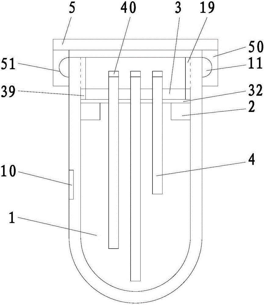
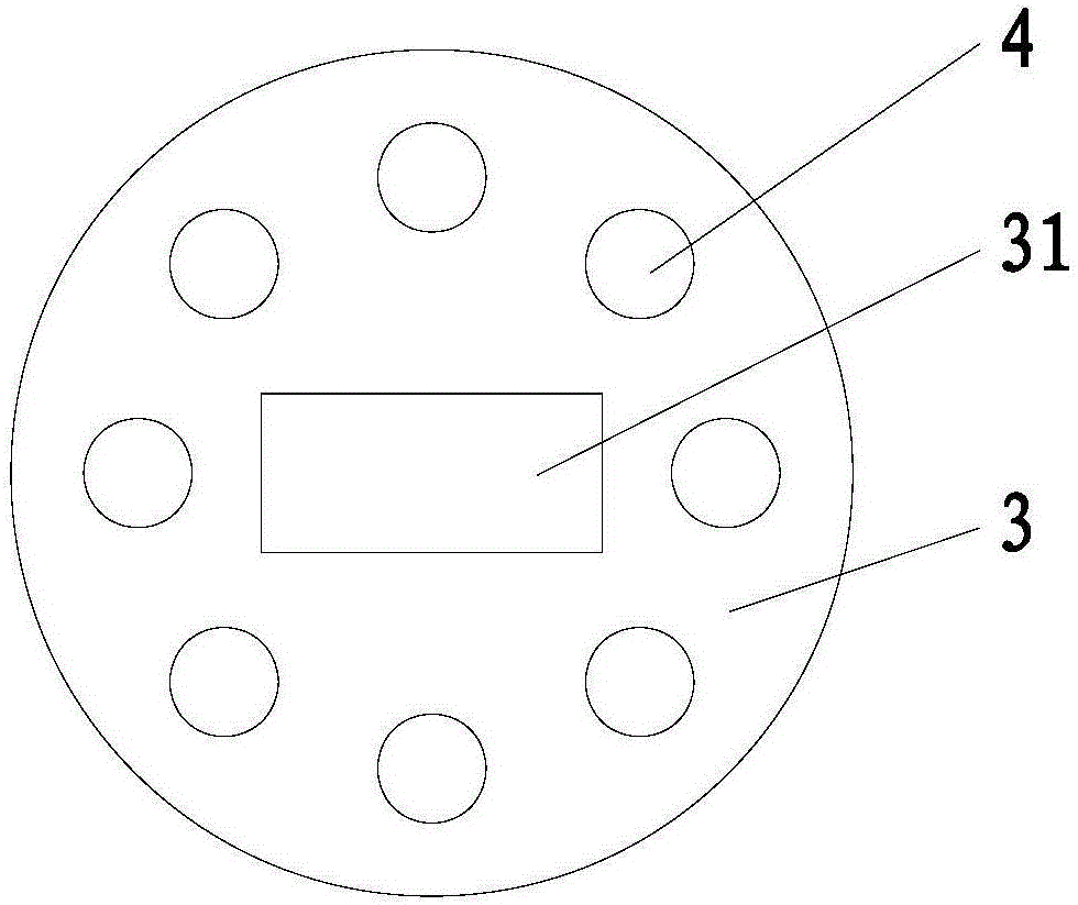
[0018] refer to figure 1 and figure 2 , a centrifuge tube that is convenient for taking liquid in the present invention, comprising a tube body 1, a cap 5, a barrier ring 2, a fixed plate 3, and a suction tube 4, a ring of barrier rings 2 is fixed on the inner wall of the tube body 1, and the tube body 1 Internal thread 19 is arranged on the inner wall, and internal thread 19 is positioned at the top of blocking ring 2, and described blocking ring 2 is covered with a fixed plate 3, and the edge of fixed plate 3 has external thread 39 that matches with internal thread 19, and described fixed plate 3 is fixed with a number of suction pipes 4 of different lengths, one end of the suction pipe 4 is located below the barrier ring 2, the other end of the washing liquid pipe is located above the fixed plate 3, and a ring of flanges is fixed on the top edge of the pipe body 1 11. There is a ring 50 at the bottom of the cap 5, and there is a ring 51 on the ring 50 that matches the fla...


PUM


Abstract

The invention discloses a centrifugal tube facilitating liquid sampling. The centrifugal tube comprises a tube body, a cap, a stop ring, a fixed disc and liquid suction tubes. The annular stop ring is fixed to the inner wall of the tube body, an internal thread is arranged on the inner wall of the tube body and located above the stop ring, the fixed disc covers the stop ring, the edge of the fixed disc is provided with an external thread matched with the internal thread, the liquid suction tubes with different lengths are fixed to the fixed disc, one end of each liquid suction tube is located below the stop ring, the other end of each liquid suction tube is located above the fixed disc, an annular flange is fixed to the edge of the top of the tube body, and an annular clamping ring is arranged at the bottom of the cap and provided with an annular clamping groove matched with the flange. Due to the fact that the liquid suction pipes with different lengths are arranged in the tube body in advance, liquid can be sampled conveniently after being centrifuged, and liquid sampling is convenient.

Description

【Technical field】 [0001] The invention relates to the technical field of medical instruments, in particular to the technical field of centrifuge tubes. 【Background technique】 [0002] A centrifuge tube is a commonly used medical device, which is mainly used for the detection of some liquid samples. The liquid in the centrifuge tube will be divided into several layers after being centrifuged by the centrifuge. After the centrifugation is completed, the liquid in different layers needs to be taken out separately. The existing centrifuge tubes take out the liquid, especially when taking out the liquid in the middle layer, the steps are cumbersome, which is not conducive to the improvement of work efficiency. 【Content of invention】 [0003] The purpose of the present invention is to solve the problems in the prior art, and propose a centrifuge tube that is convenient for taking liquid, which can make the liquid that is separated by centrifugation in the centrifuge tube easy t...

Claims


Application Information

Patent Timeline
Patent Type & Authority Applications(China)
IPC IPC(8): B01L3/14
CPCB01L3/5021
Inventor 马荣华
Owner JIANGSU KEHUA MEDICAL INSTR TECH CO LTD
Why Eureka
Try Eureka