Pipe cutting device for machining electric heating pipes

A technology of cutting device and electric heating tube, which is applied in the direction of cutting pipe device, shearing device, and accessory device of shearing machine, etc., which can solve the problems that cannot meet the needs of modern industrial production.

Inactive Publication Date: 2016-10-12
ZHENJIANG MINLE BUILDING MATERIAL CO LTD
View PDF0 Cites 6 Cited by
  • Summary
  • Abstract
  • Description
  • Claims
  • Application Information

AI Technical Summary

Problems solved by technology

The electric heating tube needs to cut off its metal tube shell during the processing, but the exis

Method used


Image

  • Pipe cutting device for machining electric heating pipes
  • Pipe cutting device for machining electric heating pipes

Examples


Embodiment Construction

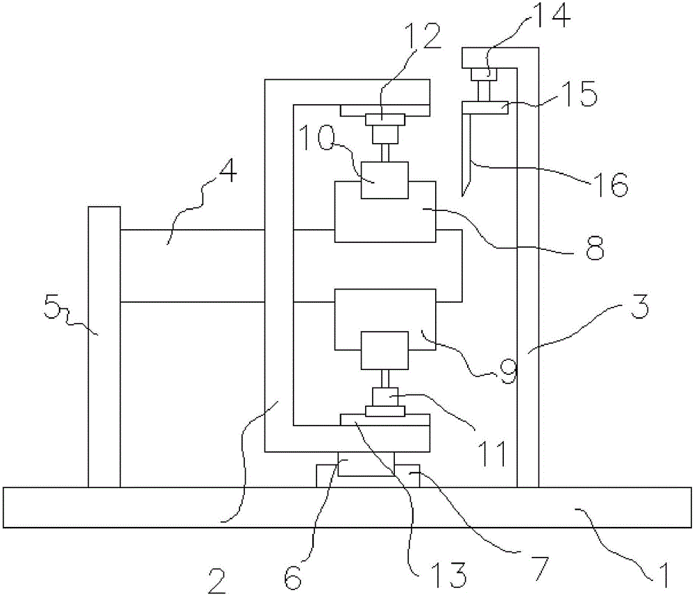
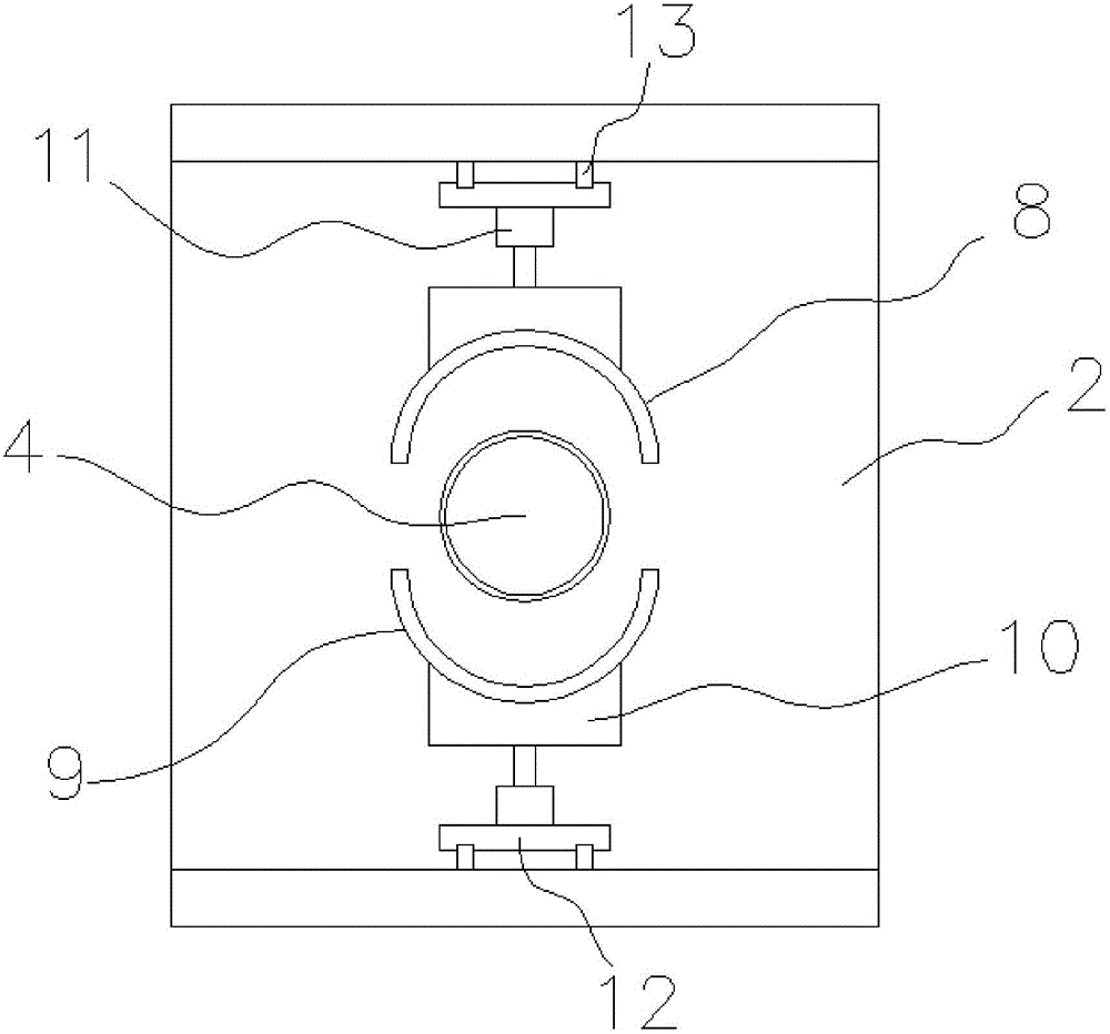
[0018] Such as figure 1 and figure 2 The shown pipe cutting device for electric heating tube processing includes a base 1, a U-shaped bracket 2, a pipe clamp, a support cylinder 4, a tool bracket 3 and a cutting tool 16, and the U-shaped bracket 2 passes through the first translation The mechanism is movably connected on the base 1, and the pipe clamp is composed of an upper clamp 8 and a lower clamp 9, and the upper clamp 8 and the lower clamp 9 are respectively connected to the upper and lower side walls of the U-shaped bracket 2 through a clamping mechanism. Above, the support cylinder 4 is placed horizontally, one end of which passes through the U-shaped bracket 2 and extends between the upper clamp 8 and the lower clamp 9, and the other end is connected with the support plate 5, and the support plate 5 is vertical Connected to the base 1, the tool holder 3 is fixedly connected to the base 1, the cutting tool 16 is installed on the tool seat 15, the tool seat 15 is conne...


PUM


Abstract

The invention relates to a pipe cutting device for electric heating tube processing, which includes a base, a U-shaped bracket, a pipe clamp, a support cylinder, a tool bracket and a cutting tool. The U-shaped bracket is movably connected to the base through a first translation mechanism. The pipe clamp is composed of an upper clamp and a lower clamp. The upper clamp and the lower clamp are respectively connected to the upper and lower side walls of the U-shaped bracket through a clamping mechanism. The support cylinder is placed horizontally, and one end of the support tube is worn The U-shaped bracket extends between the upper clamp and the lower clamp, and its other end is connected to the support plate. The support plate is vertically connected to the base, the tool bracket is fixedly connected to the base, and the cutting tool is installed On the tool seat, the tool seat is connected with the output shaft end of the hydraulic cylinder, and the hydraulic cylinder is installed on the upper end of the tool support. The design has the advantages of simple structure, easy manufacture, practicality and high efficiency.

Description

technical field [0001] The invention relates to an electric heating tube processing machine, in particular to a pipe material cutting device for electric heating tube processing. Background technique [0002] Tubular electric heating elements (electric heating tubes) are made of metal tubes (including stainless steel and copper tubes), and spiral electric heating alloy wires (nickel-chromium, iron-chromium alloy) are uniformly distributed along the central axis of the tube, and the gaps are filled and compacted to have good insulation and heat conduction. High-performance magnesia sand, both ends of the nozzle are sealed with silica gel, this metal armored heating element can heat air, metal molds and various liquids. The metal tube shell of the electric heating tube needs to be cut off during the processing, but the existing cutting device has great limitations and cannot meet the needs of modern industrial production. Contents of the invention [0003] The technical pro...

Claims


Application Information

Patent Timeline
IPC IPC(8): B23D33/10B23D21/00
CPCB23D33/10B23D21/00
Inventor 陈伟
Owner ZHENJIANG MINLE BUILDING MATERIAL CO LTD
Why Eureka
Try Eureka