machine tool

A machine tool and track technology, applied in the field of machine tools, can solve problems that require a lot of man-hours

Active Publication Date: 2018-06-29
BROTHER KOGYO KK
View PDF8 Cites 0 Cited by
  • Summary
  • Abstract
  • Description
  • Claims
  • Application Information

AI Technical Summary

Problems solved by technology

The flatness of the rail mounting surface of the X-axis rail greatly changes in the vertical direction when a heavy object such as a table is moved, therefore, especially the correction of the pitch requires a lot of man-hours

Method used


Image

  • machine tool
  • machine tool
  • machine tool

Examples


Embodiment Construction

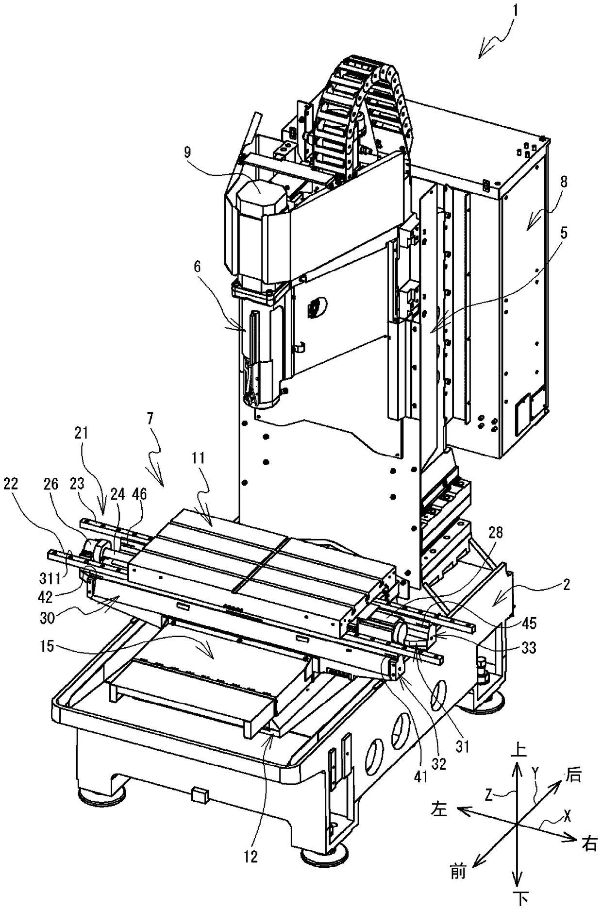
[0023] Embodiments of the present invention will be described below with reference to the drawings. In the following description, left and right, front and rear, and up and down indicated by arrows in the figure are used. The left-right direction, front-back direction, and up-down direction of the machine tool 1 are the X-axis direction, the Y-axis direction, and the Z-axis direction, respectively. figure 1 The illustrated machine tool 1 is a device that rotates a tool (not shown) attached to a spindle (not shown) at high speed to perform cutting processing on a workpiece (not shown) held on the upper surface of a table 11 .

[0024] The machine tool 1 includes a base 2, a column 5, a spindle head 6, a spindle, a table device 7, a control box 8, and the like. The base 2 is a substantially cuboid metal base extending in the front-rear direction. The column 5 is a square column erected on the rear of the top of the abutment 2 . The spindle head 6 is provided so as to be movab...


PUM


Abstract

The invention relates to a machine tool. A table device of the machine tool comprises a mobile station. The mobile station supports the table holding a workpiece to be movable in the X-axis direction. The mobile station includes a front side rail supporting portion and a rear side rail supporting portion. The front side rail supporting portion and the rear side rail supporting portion support a pair of X-axis rails. A pair of X-axis tracks guide the table in the X-axis direction. The front side rail supporting portion has grooves at both ends and at the center thereof in the longitudinal direction. The grooves extend parallel to the X-axis direction. A liner is inserted and fixed to the inside of each of the grooves at both ends of the front side rail supporting portion. An intermediate pad is inserted and fixed to the inner side of the groove in the center of the front side rail supporting portion. When the angle deviation of the front side rail supporting portion is large, the machine tool can simply correct the angular misalignment generated by the front side rail supporting portion by simply changing the spacers and the intermediate spacers having different thicknesses in the respective grooves.

Description

technical field [0001] The present invention relates to machine tools. Background technique [0002] The machine tool described in Japanese Patent Laid-Open No. 26478 2014 includes a table device. The table device supports the table so as to be movable in the X-axis direction and the Y-axis direction. The workbench device includes a base, a mobile platform and a workbench. The table fixes the workpiece on its upper surface. The base includes a pair of Y-axis guide rails on its upper surface. The Y-axis guide rail guides the mobile table in the Y-axis direction. The mobile table includes a pair of X-axis guide rails on its upper surface. The X-axis guide rail guides the table in the X-axis direction. The worktable is moved in the Y-axis direction by the moving table. Therefore, the table can move in the X-axis direction and the Y-axis direction. The Y-axis guiding rail is installed on the rail mounting surface provided on the upper surface of the base. The X-axis gui...

Claims


Application Information

Patent Timeline
Patent Type & Authority Patents(China)
IPC IPC(8): B23Q1/25B23Q1/01
CPCB23Q1/01B23Q1/017B23Q1/25
Inventor 村泽広基
Owner BROTHER KOGYO KK
Why Eureka
Try Eureka