
A kind of suction glove mold

A technology of gloves and molds, which is applied to household appliances, other household appliances, and household components, etc., can solve problems such as waste of human resources, low production efficiency, and increased cumbersome procedures, so as to improve automation and mechanization, reduce labor costs, and simplify complicated procedures. Process effect

Active Publication Date: 2017-12-19
广州市博顿运动装备股份有限公司
View PDF4 Cites 0 Cited by
  • Summary
  • Abstract
  • Description
  • Claims
  • Application Information

AI Technical Summary

Problems solved by technology

[0002] Generally, after heating and plasticizing gloves during the production process, dust particles, wool, down and other residues in the gloves need to be cleaned. In the traditional technology, the gloves are manually reversed in this process, and the suction device is used to reverse the inside of the gloves. The residue on the surface is adsorbed. In the process of inversion, the gloves on the finger part need to be filled once before they can be completely inverted. This process uses strips to fill the glove, which is prone to excessive force and the fingers will be pierced, which greatly increases errors. efficiency, and when the cleaning is not complete, an additional adhesion process is required, using glue to adhere to the surface of the reversed glove, resulting in extremely low production efficiency
There is no equipment for automatic production of this cleaning process in the traditional technology. In addition to increasing the tedious production process and wasting human resources, manual operation is not satisfactory for the cleaning effect in the glove.

Method used


Image

  • A kind of suction glove mold
  • A kind of suction glove mold

Examples


Embodiment Construction

[0016] Now the present invention is further described in conjunction with description of drawings and embodiments:

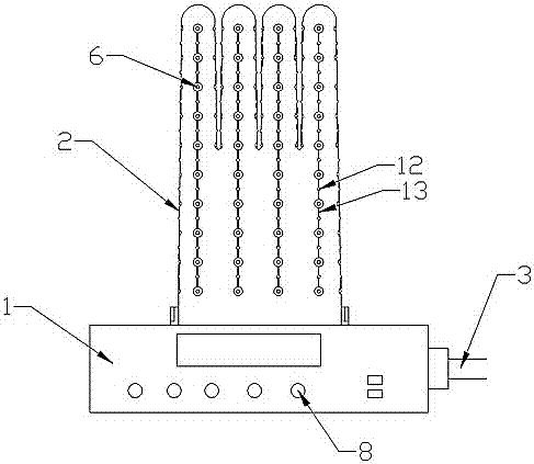
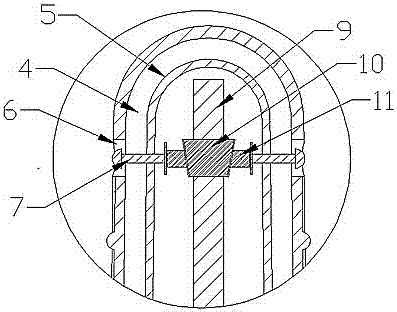
[0017] refer to figure 1 and figure 2 , a kind of air-pumping glove mold, comprising a base 1, a vacuum device and a glove mold 2, wherein: one side of the base 1 is provided with an air outlet 3, which is connected with the vacuum device, and the glove mold 2 is arranged on the side of the base 1 On the top surface, the glove mold 2 is provided with a gas flow chamber 4, the outside of the gas flow chamber 4 is the outer wall of the glove mold 2, and the inner side is the support body 5 of the glove mold 2, and the outer wall of the glove mold 2 is provided with Several air extraction holes 6 communicate with the gas flow chamber 4, and the support body 5 is provided with a support rod 7 at the center of the corresponding air extraction hole 6. The support rod 7 is a telescopic support rod, and a support ball is provided at the end of the support rod 7 .

...


PUM


Abstract

A novel air exhaust glove mold comprises a base, a vacuumizing device and a glove mold body. An air outlet is formed in one side of the base and connected with the vacuumizing device. The glove mold body is arranged on the top face of the base. An air flowing cavity is formed in the glove mold body. The outer side of the air flowing cavity serves as the outer wall of the glove mold body, and a supporting body of the glove mold body is arranged on the inner side of the air flowing cavity. A plurality of air exhaust holes are formed in the outer wall of the glove mold body to communicate with the air flowing cavity. A supporting rod is arranged at the position, corresponding to the circle centers of the air exhaust holes, of the supporting body and is a telescopic supporting rod. A supporting ball is arranged at the tail end of the supporting rod. The flowing space of dust particles in a glove is reasonably designed, automation and mechanization of the glove production process are improved, human cost is reduced, and production efficiency is improved.

Description

technical field [0001] The invention relates to a glove production device, in particular to a suction glove mold. Background technique [0002] Generally, after heating and plasticizing gloves during the production process, dust particles, wool, down and other residues in the gloves need to be cleaned. In the traditional technology, the gloves are manually reversed in this process, and the suction device is used to reverse the inside of the gloves. The residue on the surface is adsorbed. In the process of inversion, the gloves on the finger part need to be filled once before they can be completely inverted. This process uses strips to fill the glove, which is prone to excessive force and the fingers will be pierced, which greatly increases errors. The efficiency is high, and when the cleaning is incomplete, an additional adhesion process is required, and the glue is used to adhere the surface of the reversed glove, resulting in extremely low production efficiency. There is ...

Claims


Application Information

Patent Timeline
Patent Type & Authority Patents(China)
IPC IPC(8): B29C41/34B29C41/40B29L31/48
CPCB29C41/34B29C41/40B29L2031/4864
Inventor 刘旭峰
Owner 广州市博顿运动装备股份有限公司
Learn More