Precision winder for winding yarns

A winder and precise technology, applied in the field of placing equipment, can solve the problems of difficulty in taking out yarn, easy moldy winch, easy wear and damage of wooden winch, etc., to achieve the effect of easy removal

Active Publication Date: 2016-10-12
XINCHANG WANSHIFA TEXTILE MACHINERY
View PDF8 Cites 10 Cited by
  • Summary
  • Abstract
  • Description
  • Claims
  • Application Information

AI Technical Summary

Problems solved by technology

[0002] The outer diameter of the existing hank creel is fixed, and it is necessary to use a hank creel with a different diameter for different yarns or needs. Therefore, a large number of hank creels are stored in the spinning enterprise, occupying a large area. space, and the wooden skein frame is prone to mold during long-...

Method used


Image

  • Precision winder for winding yarns
  • Precision winder for winding yarns
  • Precision winder for winding yarns

Examples


no. 1 example

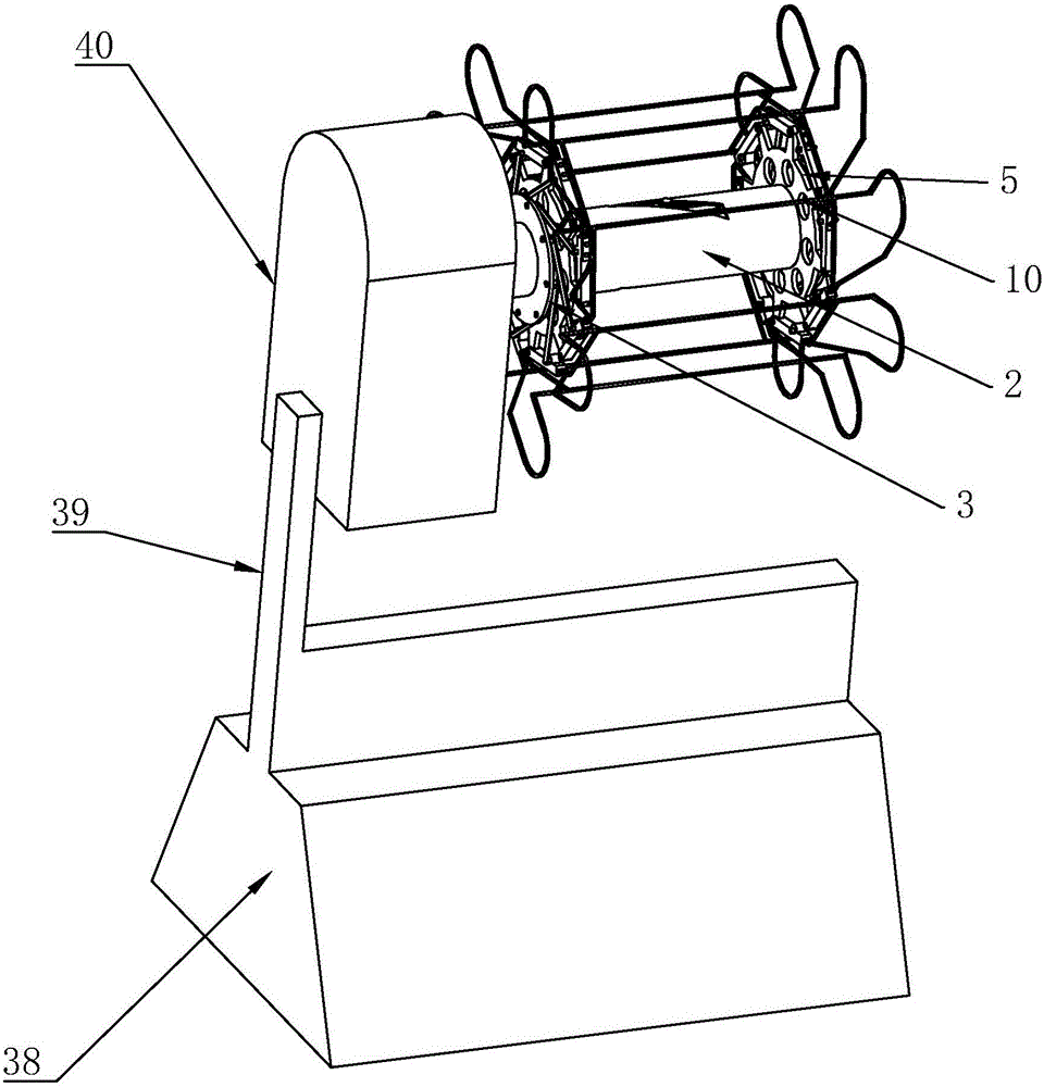
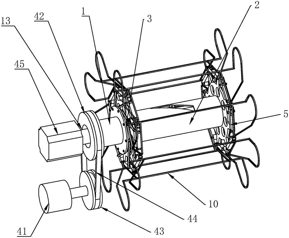
[0051] refer to Figures 1 to 8 As shown, a skein precision winding machine in this embodiment includes a base 38, a support rod 39 is arranged on the base 38, a mounting cover 40 is arranged on the support rod 39, and a mounting cover 40 is arranged inside the mounting cover 40 There is a cylinder 45 and a motor 41. The installation cover 40 is provided with an inner cylinder 1 and an outer cylinder 2 sleeved outside the inner cylinder 1. The inner cylinder 1 passes through the two ends of the outer cylinder 2 and the outer cylinder 2 The end of the cylinder 2 is provided with a first installation ring 3, and the first installation ring 3 is provided with a plurality of first installation holes 4, and the edge of the outer cylinder 2 is provided with a second installation ring 5, and the second installation ring 5 is hinged with a movable block 6, the movable block 6 is provided with a second mounting hole 7, the movable block 6 and the first mounting ring 3 are provided with...

Embodiment 2

[0070] refer to Figures 9 to 14 ,

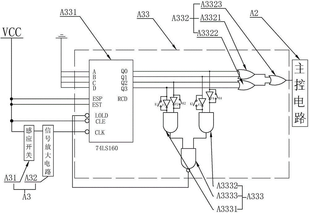
[0071] On the basis of the first embodiment, the base is further provided with an installation mechanism B0 for installing the winding, and the installation mechanism B0 includes a housing B1.

[0072] A control circuit is also provided in the installation mechanism, and the control circuit includes:

[0073] The drive circuit A1 is coupled to the motor to drive the motor to run;

[0074] The main control circuit A2 is coupled to the driving circuit A1 to send a driving signal to the driving circuit A1 to make the driving circuit A1 drive the motor to run, and is also coupled to the external yarn clearer to receive the yarn detection signal sent by the yarn clearer ;

[0075] The detector 3 is set on the winding seat to detect the number of winding replacements, and is also coupled to the main control circuit A2, so as to send the detected winding quantity signal to the main control circuit A2. In the process, firstly, the main control ...

specific Embodiment approach

[0090] As an improved specific implementation, the energy storage circuit A11 includes:

[0091] A diversion diode D, the anode of the diversion diode D is coupled to the motor and grounded;

[0092] A switch tube Q, the switch tube has a first terminal, a second terminal and a control terminal, wherein the control terminal is coupled to the main control circuit A2, the first terminal is coupled to the cathode of the drain diode D, and the second terminal is coupled to the storage The energy capacitor C is coupled between the magnetic switch of the relay K and the motor. The switch tube is a PMOS tube. When the motor stops, the internal coil of the motor will release electric energy, and the switch tube Q is turned on, and the electric energy will be drained Under the action of the diode D, it flows through the switching tube Q into the energy storage capacitor C, and is stored by the energy storage capacitor C. When it needs to be restarted, the energy storage capacitor C wil...


PUM


Abstract

The invention discloses a precision winder for winding yarns. The precision winder comprises an inner cylinder and an outer cylinder, wherein the outer cylinder sleeves outside the inner cylinder; the inner cylinder penetrates through two ends of the outer cylinder; first mounting rings are arranged at the end penetrating through the outer cylinder; a plurality of first mounting holes are formed in each first mounting ring; second mounting rings are arranged at the outer edge of the outer cylinder; movable blocks are articulated with the second mounting rings; second mounting holes are formed in the movable blocks; connection rods are arranged on the movable blocks and the first mounting rings; insertion rods are arranged at two ends of each connection rod respectively; one insertion rod is inserted into a first mounting hole; the other insertion rod is inserted into a second mounting hole; a bracket used for winding yarns is arranged on each movable block; one end of each bracket is fixedly arranged on a movable block of a second mounting ring; the other end of each bracket is fixed to a movable block of the other second mounting ring. Through the precision winder for winding yarns, the required periphery diameter is controlled according to the requirement of actual production; different-sized yarns are conveniently wound; meanwhile, the movable blocks are folded after finishing winding the yarns; the wound yarns in tight state can be released.

Description

technical field [0001] The invention relates to a placement device, more specifically to a hank yarn precision winder. Background technique [0002] The outer diameter of the existing hank creel is fixed, and it is necessary to use a hank creel of different diameters for different yarns or requirements. Therefore, a large number of hank creels are stored in spinning enterprises, occupying a large area. Space, and the wooden creel is prone to mold during long-term storage, especially in the south, where the weather is humid, and the wooden creel is most likely to be worn and damaged. [0003] Especially because the outer diameter of the strangle frame is fixed, in the process of completing the skein, the yarn taking process is difficult to take the yarn due to the effect of the yarn pre-tightening force. Contents of the invention [0004] Aiming at the deficiencies in the prior art, the object of the present invention is to provide a hank yarn precision winding machine whi...

Claims


Application Information

Patent Timeline
IPC IPC(8): B65H75/24
CPCB65H75/24B65H2701/31
Inventor 徐属斌王伟军徐良耀
Owner XINCHANG WANSHIFA TEXTILE MACHINERY
Why Eureka
Try Eureka