[0017] The present invention will now be further described with reference to the drawings.
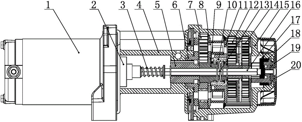
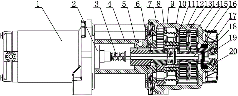
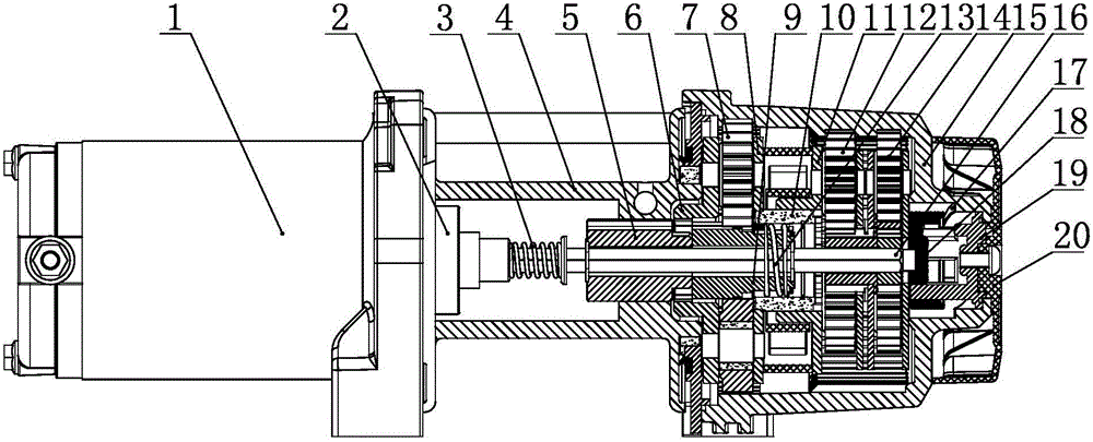
[0018] Such as Figure 1-4 As shown, the electric two-speed winch includes a winch support, a motor 1, a transmission shaft 16, a hoisting drum 4, a reduction gear box 15, and a station control mechanism. The reduction gearbox is equipped with 14 primary planetary gear sets, secondary planetary gear assemblies 12, and tertiary planetary gear assemblies 7. The motor is connected to one end of the drive shaft through a back-stop clutch 2, and the other end of the drive shaft is connected through a primary center wheel drive. The first-stage planetary gear assembly, the first-stage planetary gear assembly, the second-stage planetary gear assembly, and the third-stage planetary gear assembly are connected in sequence to form a reduction transmission. Among them, the first-stage planetary gear assembly and the second-stage planetary gear assembly form two through existing conventional connections. The transmission structure of the invention is adopted between the two-stage planetary gear assembly and the third-stage planetary gear assembly. Specifically, the transmission shaft is axially sleeved with the three-stage center wheel 9 of the three-stage planetary gear assembly, and the third-stage center wheel is positioned to move and rotate relative to the transmission shaft by a circlip, and the third-stage center wheel is provided with steps along the axial direction. The three sections of the formula are the left section 901, the middle section 902, and the right section 903. The radial dimensions of the left section, the middle section, and the right section are gradually reduced. The left section meshes with the planetary gear in the three-stage planetary gear assembly, and the right The outer part of the section is sequentially sleeved with the left washer 21, the spring 13, and the right washer 22, and the end of the right section is connected with the snap ring 24. The spring is limited to the left and right washer, and the left washer is limited to the right end of the middle section. The right washer is limited to the snap ring; the spring outer ring is sleeved with spline 10, the left end of the spline inner ring is provided with an inner gear ring 1001 meshing with the left section of the three-stage center wheel, and the spline inner ring is near the right end A retaining ring 23 that limits the right side of the right shim is provided. The left end of the spline outer ring is provided with external teeth that mesh with the right bracket of the three-stage planetary gear of the three-stage planetary gear assembly. The retaining ring and snap ring limit the right shim. Do not interfere with each other when positioning, the spline inner ring gear and the middle section of the three-stage center wheel do not interfere with each other when they limit the left shim; the right end of the spline outer ring and the secondary planetary wheel left bracket 11 of the secondary planetary gear assembly keep moving Plug-in transmission connection, when the left end of the spline moves along the axial direction with the drive shaft, three states are formed. The first state is the meshing transmission of the spline and the left section of the third-stage center wheel, and the second state is the left side of the spline and the third-stage center wheel. The right bracket 8 of the three-stage planetary gear and the three-stage planetary gear are not engaged, and the third state is the spline and the third-stage planetary gear right support meshing transmission. Among them, the state 1 and state 3 correspond to the two moving stations of the drive shaft, namely the high-speed station and Low-speed station, state two is the intermediate state of switching between state one and state three.
[0019] In addition to the above two moving stations, the transmission shaft 16 is also provided with a clutch station. The three-stage planetary wheel left support 6 of the three-stage planetary gear assembly 7 and the hoisting drum 4 are connected by a rectangular spline 5 for transmission. The key is sleeved on the drive shaft and is positioned by the circlip to rotate. When the drive shaft moves to the clutch position, the rectangular spline keeps meshing and driving with the hoisting drum, but disengages from the left bracket of the three-stage planetary gear. When the drive shaft moves When reaching the low-speed and high-speed stations of the winch, the rectangular spline is simultaneously engaged with the left support of the three-stage planetary gear and the hoisting drum.
[0020] In order to realize the switch between the clutch, low speed and high speed of the winch, the electric double-speed winch also includes a station control mechanism that controls the drive shaft to move in the axial direction. The station control mechanism is located at the end of the reduction gear box 15, which includes a dial Hand 20, shift fork 19, clutch seat 18, the shifting hand is fixedly connected to the shift fork, the shift fork and the clutch seat are all rotatably positioned in the end chamber of the reduction gearbox, and the shift fork and the clutch seat are connected and rotated synchronously , And the insertion direction is parallel to the axis of the transmission shaft, and the end surface of the clutch seat is positioned against the end of the transmission shaft. The end chamber of the reduction gearbox is provided with a rotating ramp 17 that pushes the clutch seat to move along the axis of the drive shaft when the clutch seat rotates. The motor is connected to the transmission shaft 16 through the non-return clutch 2. The transmission shaft is in a telescopic fit with the non-return clutch. The transmission shaft is sleeved with a return spring 3. One end of the return spring is located at the end of the non-return clutch and the other end passes through the transmission shaft. The circlip is connected, and the end face of the return spring is tightly restricted by the circlip.
[0021] In combination with the above structure, the working principle of the present invention is: the station control mechanism controls the transmission shaft 16 to move axially between the motor 1 and the dial 20 to form a clutch station, a high-speed station, and a low-speed station. In the initial state, the drive shaft is located at the clutch station, such as image 3 As shown, at this time, since the left bracket of the three-stage planetary wheel is disengaged from the rectangular spline 5, the left bracket 6 of the three-stage planetary wheel fails to transmit power to the hoisting drum 4 through the rectangular spline, and the hoisting drum is free to rotate for At the same time, the spline 10 is in the third state, that is, the left end of the spline is engaged with the right support of the three-stage planetary gear. When the control lever 20 rotates forward, the lever drives the shift fork 19 and the clutch seat 18 to rotate, and the clutch seat moves along the rotary ramp 17. Under the action of the return spring 3, the drive shaft is pushed to move in the direction of the dial, and the drive shaft drives the rectangle The spline and the three-stage center wheel 9 move together until the rectangular spline is engaged with the three-stage planetary wheel left support 6, the hoisting drum transmission, and the inner gear ring 1001 of the spline is on the left washer 21, the spring 13, and the right washer 22. Under the tightening action of the snap ring 24, the outer teeth at the left end of the spline keep meshing with the right bracket 8 of the three-stage planetary gear, and the high-speed station is reached at this time, such as figure 2 As shown, in this station, the rotation of the drive shaft only drives the primary planetary gear assembly 14 and the secondary planetary gear assembly 12 to achieve secondary deceleration. The secondary planetary gear assembly and the tertiary planetary gear assembly 7 rotate synchronously through splines , So the hoisting drum rotates at a high speed. In the initial state, when the control dial is reversed, the dial drives the shift fork and the clutch seat to rotate, and the clutch seat moves along the rotating ramp. Under the action of the return spring, the transmission shaft moves in the direction of the dial, and the transmission shaft drives the rectangular spline. It meshes with the three-stage planetary gear left support and hoisting drum transmission. At the same time, the transmission shaft drives the three-stage center wheel. The third-stage center wheel is pressed by the spline inner gear ring, spring, right washer, and retaining ring. Drive the spline to move synchronously until the external teeth on the left end of the spline are disengaged from the right bracket of the three-stage planetary gear, that is, the spline reaches the state two and remains, and then the three-stage center wheel is pushed by the elastic force of the return spring. Segment 901 meshes with the inner gear ring of the spline, that is, the spline reaches state one and reaches the low-speed station, such as figure 1 As shown, in this station, the rotation of the transmission shaft drives the first-stage planetary gear assembly, the second-stage planetary gear assembly, and the third-stage planetary gear assembly in turn to achieve three-stage deceleration, and the hoisting drum rotates at a low speed. When the reverse operation is dialed, the work position can be reversed.
[0022] The above content is intended to illustrate the technical means of the present invention, but not to limit the technical scope of the present invention. Those skilled in the art can make obvious improvements to the present invention in combination with existing common knowledge. For example, the order of the high and low positions of the winch can be achieved by changing the direction of the handle and the rotating ramp structure of the clutch seat. Such improvements also fall into the present invention. Within the scope of protection.