Magnetic adsorption geometric cutting device
A cutting device and magnetic adsorption technology, applied in the field of clothing cutting, can solve problems such as slow cutting speed, jagged edges, and straight lines are not straight enough, and achieve the effect of fast cutting speed and neat knife marks
- Summary
- Abstract
- Description
- Claims
- Application Information
AI Technical Summary
Problems solved by technology
Method used
Image

Examples
Embodiment 1
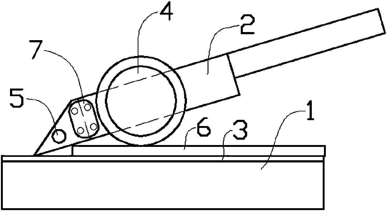
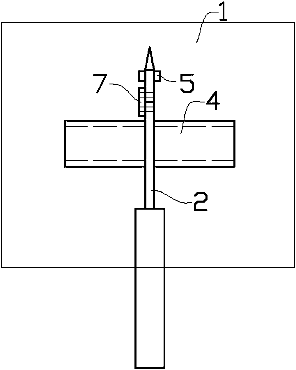
[0018] Such as figure 1 , figure 2 As shown in the embodiment, the magnetic adsorption geometric cutting device includes a magnetic plate 1 and a cutting knife 2. The magnetic plate 1 is placed horizontally, and its upper part is covered with an iron metal plate 3. The front part of the cutting knife 2 is designed It is a blade, and the rear part is designed as a knife handle. The blade position at the front part of the cutting knife 2 is equipped with a guide roller 4 that can rotate from the axis horizontally. The guide roller 4 is made of iron material, and the lower end of the guide roller 4 Lower than the lower position when the blade blade is placed horizontally, the upper part of the front end blade position of the blade is equipped with an adsorption block 5 of iron material. The guide roller 4 is cylindrical, and the guide roller 4 is installed on the left and right sides of the cutting knife 2 respectively. In specific design, the handle of the scissors 2 is made ...
Embodiment 2
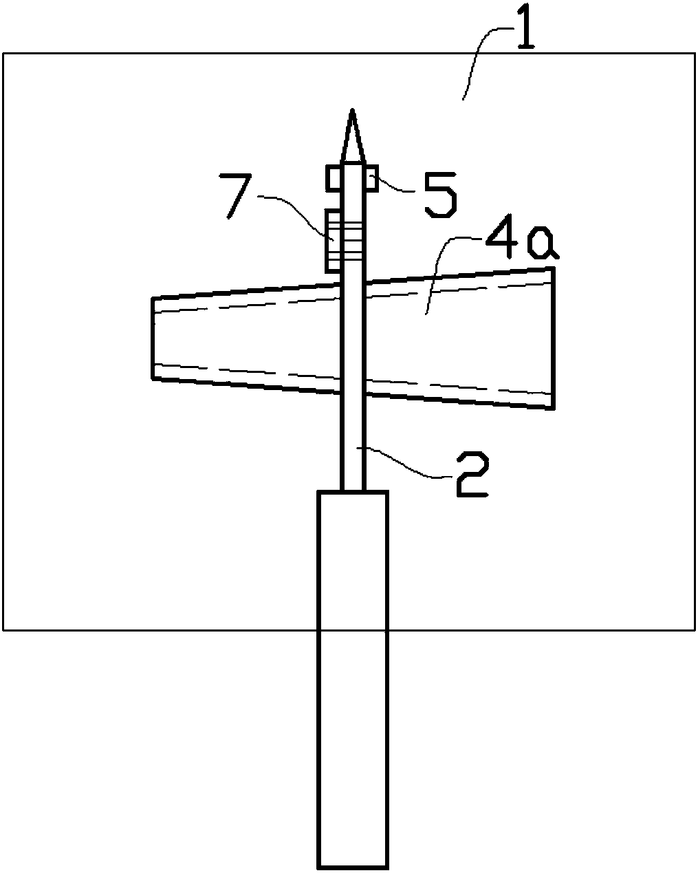
[0023] Such as image 3 As shown, in this embodiment, the guide rollers 4a are respectively installed on both sides of the blade of the cutting knife 2 . The guide rollers 4a on both sides of the blade of the scissors 2 are in the shape of a truncated cone. The guide roller 4a on the left and the guide roller 4a on the right form a complete truncated cone shape by the cutting knife 2 . The structure of the rest of the device is the same as that of the embodiment. During use, the guide roller 4a of circular truncated shape and adsorption block 5 are adsorbed on the iron plate 3 on the cutting knife 2 blade, when pulling the knife handle on the cutting knife 2 to move backward because the guiding roller 4a is circular truncated shape, described cutting knife 2. Move along the arc shape, so that you can easily cut out fan-shaped or circular sizes; and the cutting marks are neat. Compared with scissors cutting, using a knife to cut directly is faster. The guide roller 4a is ass...
Embodiment 3
[0025] Such as Figure 4 As shown, in this embodiment, the two guide rollers 4b on both sides of the blade of the cutting knife 2 are in the shape of a truncated cone with the same size. One end of the guide roller 4 b with a larger area is close to the blade side of the cutting knife 2 . The structure of the rest of the device is the same as that of the embodiment. During use, the guide roller 4b on one side of the blade of the cutting knife 2 is close to the iron plate 3, and the other guide roller 4b is tilted up, so that the cutting knife 2 can be pulled to cut out the arc shape, and when the user will cut When the guide roller 4b on the other side of the blade of the scissors 2 is pressed down and adsorbed onto the iron plate 3, the guide roller 4b on the side that has just been attached to it is tilted up, so that it can cut in the tangential direction of the arc shape just cut out. By forming an arc opposite to the arc, the wavy edge can be cut conveniently and accura...
PUM
 Abstract
Description
Claims
Application Information
 - R&D
- Intellectual Property
- Life Sciences
- Materials
- Tech Scout
- Unparalleled Data Quality
- Higher Quality Content
- 60% Fewer Hallucinations
Browse by: Latest US Patents, China's latest patents, Technical Efficacy Thesaurus, Application Domain, Technology Topic, Popular Technical Reports.
© 2025 PatSnap. All rights reserved.Legal|Privacy policy|Modern Slavery Act Transparency Statement|Sitemap|About US| Contact US: help@patsnap.com