
Valve control adjustment mechanism, adjustment method and engine

A technology for controlling adjustment and valves, which is applied in the direction of machines/engines, engine components, mechanical equipment, etc. It can solve problems such as complex structure, uncompact structure, and bulky volume, and achieve the effect of convenient adjustment and improved intake and exhaust efficiency

Active Publication Date: 2018-10-30
CHONGQING JIAOTONG UNIVERSITY
View PDF4 Cites 0 Cited by
  • Summary
  • Abstract
  • Description
  • Claims
  • Application Information

AI Technical Summary

Problems solved by technology

[0003] 1. The traditional camshaft valve control system is bulky and complex in structure. Due to the limitation of the cylinder arrangement and the crankshaft structure, the traditional air distribution system and the crankshaft have different axes, and the air distribution system must be driven through a complex synchronous transmission mechanism, so that the air distribution system become complex and not compact
[0004] 2. The control cam of the traditional camshaft valve control system is integrated on the camshaft. One exhaust cylinder corresponds to one camshaft. When there are many cylinders, more cylinders are required, and multiple sets of camshafts and their drive systems are required, which has a huge structure.
It is quite difficult to realize the dynamic adjustment of valve lift and valve opening and closing timing, but the valve lift and opening and closing timing have a great influence on the intake and exhaust efficiency of the engine

Method used


Image

  • Valve control adjustment mechanism, adjustment method and engine
  • Valve control adjustment mechanism, adjustment method and engine
  • Valve control adjustment mechanism, adjustment method and engine

Examples


Embodiment Construction

[0043] The technical solutions of the present invention will be clearly and completely described below in conjunction with the accompanying drawings. Apparently, the described embodiments are some of the embodiments of the present invention, but not all of them. Based on the embodiments of the present invention, all other embodiments obtained by persons of ordinary skill in the art without making creative efforts belong to the protection scope of the present invention.

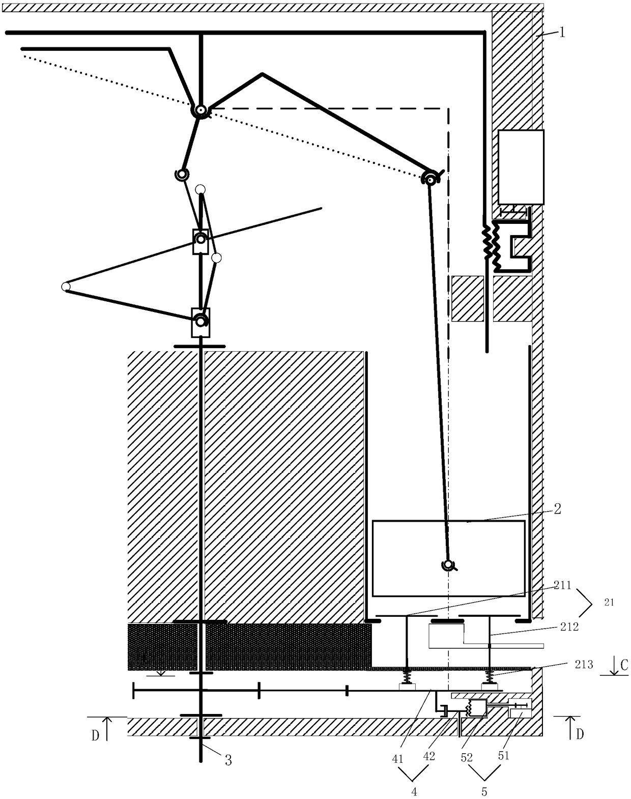
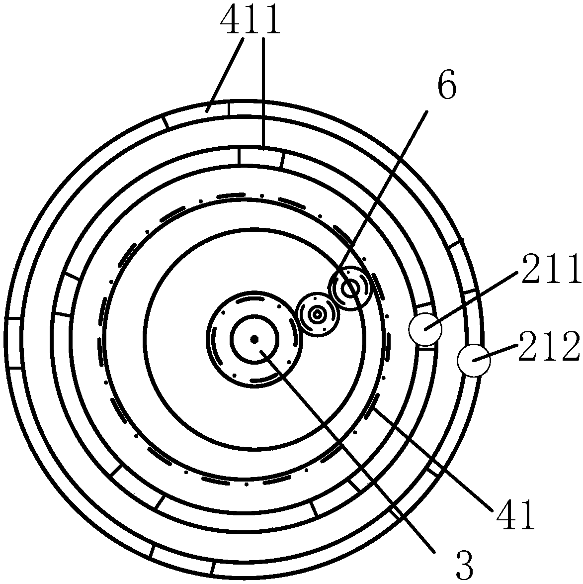
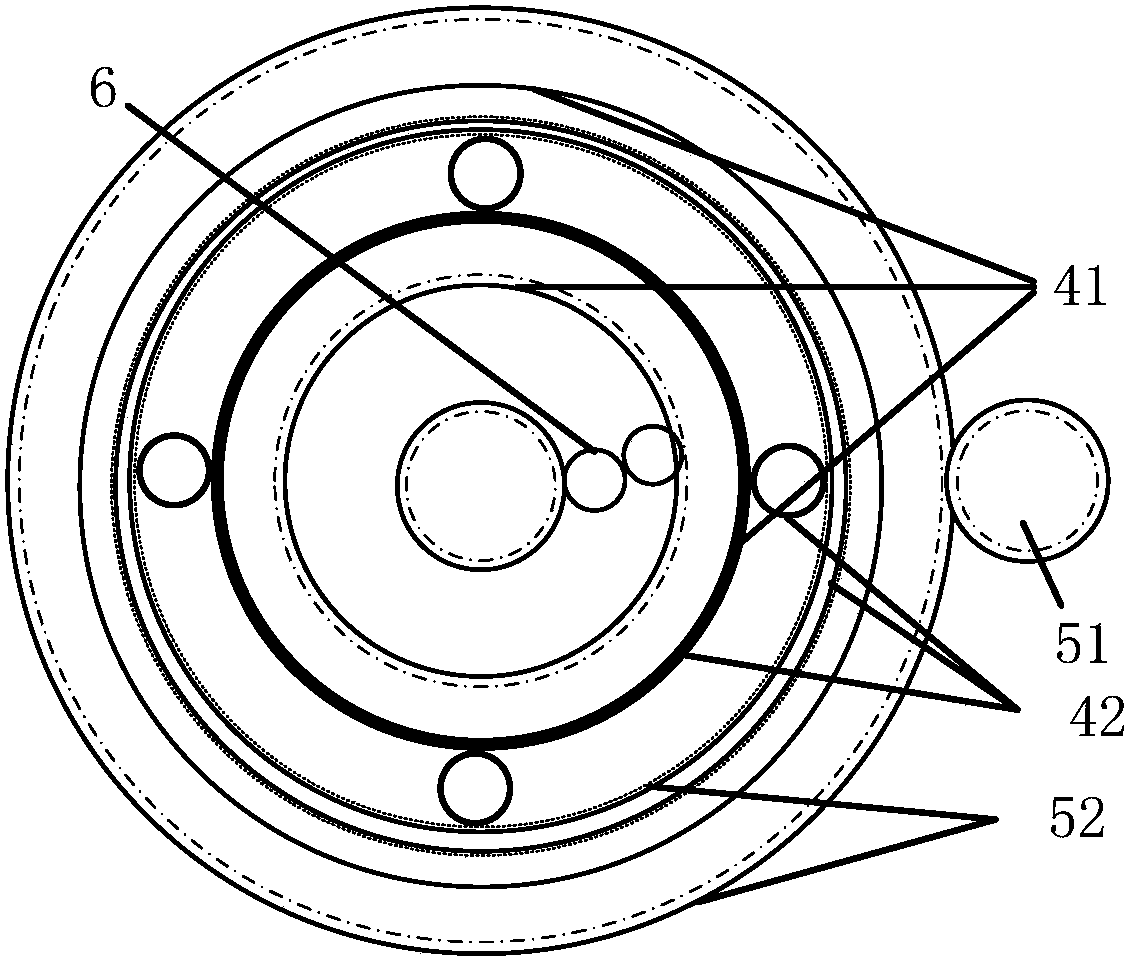
[0044] Please refer to Figure 1 to Figure 4 ;

[0045] The valve control adjustment mechanism provided by the present invention includes:

[0046] The piston and cylinder assemblies 2 are distributed in an array in the circumferential direction of the main shaft 3 of the engine, and include cylinders, pistons, valve assemblies 21 and the like.

[0047] The valve control device 4 is connected with the main shaft 3, and the valve control device 4 includes a valve control flywheel 41 and a flywheel mounting se...


PUM


Abstract

The invention discloses a valve control adjusting mechanism and method and an engine. The valve control adjusting mechanism comprises piston air cylinder assemblies, a valve control device and a plurality of protrusions; the piston air cylinder assemblies are distributed in the circumferential direction of a spindle in an array mode, the valve control device is connected with the spindle and comprises a valve control flywheel and a flywheel mounting seat which are connected through a rotary pair, and the protrusions are arranged on the upper end face of the valve control flywheel in the circumferential direction and are in butt joint with valve assemblies in the piston air cylinder assemblies. According to the scheme, the spindle drives the valve control flywheel to rotate, and the valve assemblies are controlled to be opened and closed through the protrusions. Coaxial control over opening and closing of the valve assemblies is achieved, the valve stroke and opening and closing opportunities are very convenient to adjust and are adjusted according to the work state of the engine in real time, and the intake and exhaust efficiency is improved.

Description

technical field [0001] The invention relates to the technical field of engines, in particular to a valve control adjustment mechanism, an adjustment method of the adjustment mechanism and an engine applying the above adjustment structure. Background technique [0002] At present, the camshaft valve control system is an essential part of most piston engines. The valve control system controls the cooperation between the valve and the cylinder assembly, and important parameters such as valve lift and opening and closing timing have a great impact on engine performance. . The traditional camshaft valve control system has the following disadvantages: [0003] 1. The traditional camshaft valve control system is bulky and complex in structure. Due to the limitation of the cylinder arrangement and the crankshaft structure, the traditional air distribution system and the crankshaft have different axes, and the air distribution system must be driven through a complex synchronous tran...

Claims


Application Information

Patent Timeline
Patent Type & Authority Patents(China)
IPC IPC(8): F01L13/00F01L1/46
CPCF01L1/46F01L13/00
Inventor 柳平
Owner CHONGQING JIAOTONG UNIVERSITY
Learn More