
Double-convex-curved-surface contact sleeve steering structure of supporting column for tidal-current-energy generator set

A generator set and tidal current energy technology, which is applied in the direction of hydropower, engine components, machines/engines, etc., can solve the problems that the direction of the water turbine cannot be changed, and the generator set cannot use the tidal current to the greatest extent, so as to improve the service life and reduce the Abrasion, rotation and flexible effects

Inactive Publication Date: 2016-10-12
HARBIN ELECTRIC MASCH CO LTD
View PDF5 Cites 1 Cited by
  • Summary
  • Abstract
  • Description
  • Claims
  • Application Information

AI Technical Summary

Problems solved by technology

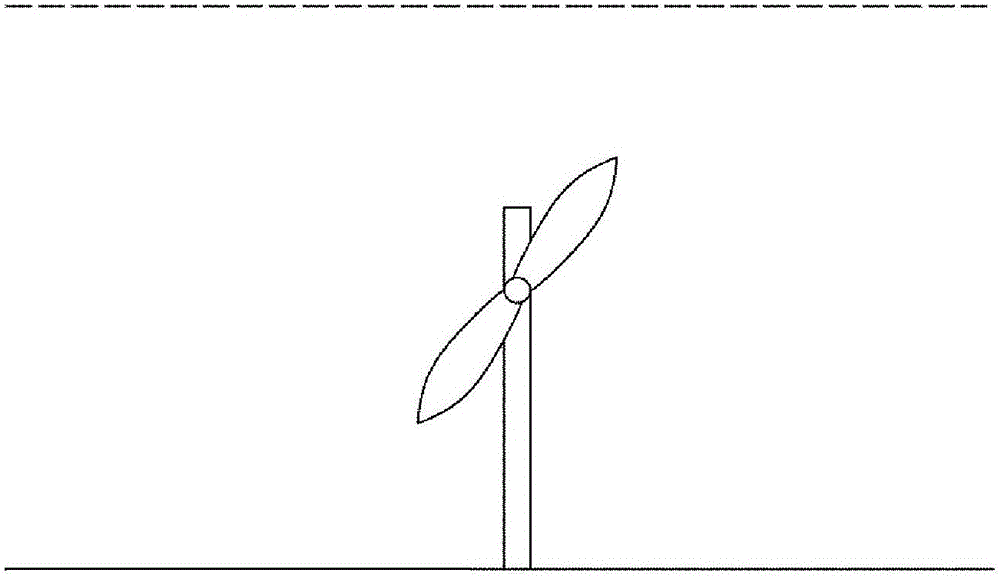
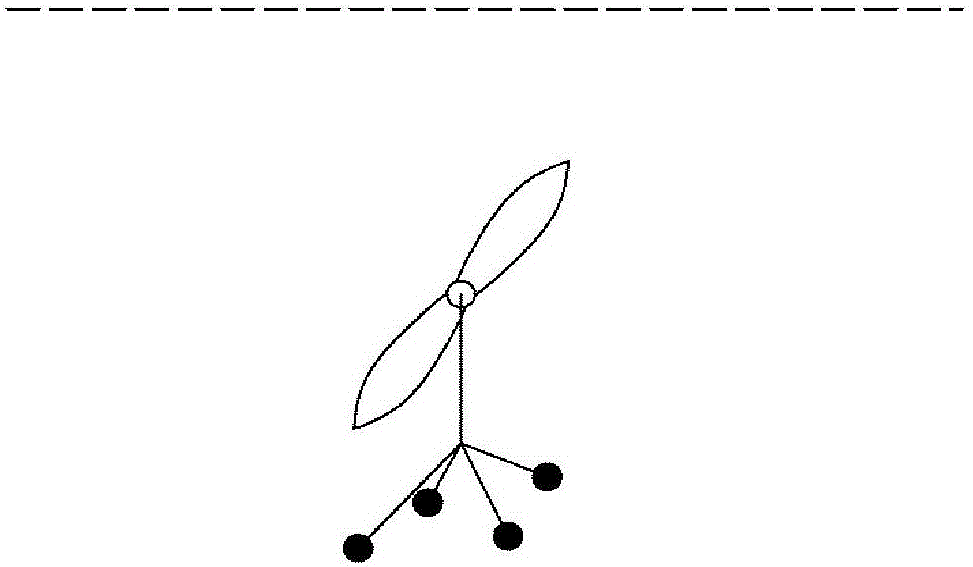
It can be seen from the figure that these structures can complete the collection and conversion of tidal current energy, but none of them can change the direction of the turbine, and can only accept the energy of the tidal current in a directional way, which leads to the inability of the generator set to utilize the energy of the tidal current to the greatest extent.

Method used


Image

  • Double-convex-curved-surface contact sleeve steering structure of supporting column for tidal-current-energy generator set
  • Double-convex-curved-surface contact sleeve steering structure of supporting column for tidal-current-energy generator set
  • Double-convex-curved-surface contact sleeve steering structure of supporting column for tidal-current-energy generator set

Examples


Embodiment Construction

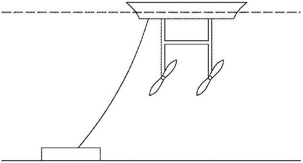
[0026] The double-convex surface contact sleeve steering structure of the tidal current energy generating set pillar, such as Figure 4 As shown, in the structure of the single-column double-spread tidal current energy generator set, the whole unit is a truss structure 2, the upper part of the unit has a working platform 1, and the upper part of the generator set 5 with blades 4 is installed with two cross-sections in the shape of an airfoil. 5. The pipeline stretches upwards at the beginning and spreads its wings 3; the unit base 8 is equipped with a pillar 9, and the top of the pillar 9 is in the shape of a curved surface 10; the main shaft 7 is fitted with a sleeve 11, and the sleeve 11 is equipped with a shaft sleeve 12; Cover 12 forms steering mechanism 6. The upper end of the main shaft 7 is connected to the lower part of the generator set 5, and the curved surface 17 of the lower end of the main shaft 7 is supported on the pillar 9 below, and the highest point 13 of the...


PUM


Abstract

The invention relates to a double-convex-curved-surface sleeve steering structure of a supporting column for a tidal-current-energy generator set. On a supporting column of a single-column double-expansion type tidal-current-energy generator set, the way that two curved surfaces are in contact with each other in a point-to-point manner, a main shaft and a sleeve are of an integrated structure, the upper end of the main shaft is connected with the tidal-current-energy generator set, and then the supporting column is inserted into the sleeve is adopted. The supporting column at a lower end is fixedly arranged on a submarine truss mechanism. In such a way, the tidal-current-energy generator set part can be enabled to be separated from an integral truss; and an upper part of the tidal-current-energy generator set can be hoisted, so as to realize the function of carrying out lifting by using a sea-level platform. The sleeve which is connected with the main shaft together and the curved-surface design of the upper end of the supporting column in the double-convex-curved-surface sleeve steering structure of the supporting column for the tidal-current-energy generator set can play a guiding role; the maintenance is convenient; the contact area of a point-to-point structure of a curved-surface supporting structure is minimum; friction moment during relative rotation can be reduced; a double-convex-curved-surface supporting structure is quite simple, and can adapt to severe working environments in seawater; and meanwhile, grooves in the structure can be used for completing the self-blowdown function of the double-convex-curved-surface sleeve steering structure.

Description

Technical field: [0001] The invention relates to a double-convex curved surface contact sleeve steering structure of a tidal current energy generating set pillar. Background technique: [0002] Since the 21st century, in the face of the depletion of conventional energy and the deterioration of the environment, countries have turned their attention to renewable energy. Ocean tide energy has become a key research object because of its superior renewability, environmental protection and huge storage capacity. However, compared with land power construction, the tidal current energy development environment is harsh and the energy density is low. At the same time, the flow direction of the tidal current will change during the operation of the unit, resulting in the change of the optimal working position of the hydro turbine. If the generating set cannot adjust the direction of the turbine, then the tidal current energy cannot be maximized. Common tidal current energy generators ...

Claims


Application Information

Patent Timeline
IPC IPC(8): F03B11/00F03B13/12
CPCF03B11/00F03B13/12Y02E10/20
Inventor 覃大清赵越张锐刘登峰刘永新李正东庞立军
Owner HARBIN ELECTRIC MASCH CO LTD
Learn More