A test system and test method for a vehicle-mounted sliding vane air compressor

An air compressor and testing system technology, which is applied in pump testing, liquid variable capacity machinery, mechanical equipment, etc., can solve the problems of inability to evaluate the performance of the whole machine, low measurement efficiency, and high cost, and achieve integrated parameter testing Problems, simple and convenient operation, and the effect of reducing testing costs

Active Publication Date: 2017-12-29
吴泰 +1
View PDF7 Cites 0 Cited by
  • Summary
  • Abstract
  • Description
  • Claims
  • Application Information

AI Technical Summary

Problems solved by technology

The current test system only evaluates a single performance parameter, such as the flow index, which is the focus of every customer of the air compressor. At present, most air compressor factories use standard nozzle flowmeters to measure, but this measurement The method has low measurement efficiency and high cost, and is not suitable for mass production
This single performance measurement method is not only low in efficiency and high in cost, but more importantly, it cannot establish the correlation between various performance parameters, and cannot guarantee the consistency between the measurement parameters and the performance parameters of the air compressor in the actual operation process, so it cannot be verified Systematic evaluation of the performance of the whole machine during operation, especially for vehicle-mounted air compressors

Method used


Image

  • A test system and test method for a vehicle-mounted sliding vane air compressor
  • A test system and test method for a vehicle-mounted sliding vane air compressor
  • A test system and test method for a vehicle-mounted sliding vane air compressor

Examples


Embodiment Construction

[0028] The embodiments of the present invention will be described in detail below. This embodiment is implemented on the premise of the technical solution of the present invention. Detailed implementation modes and specific operation procedures are given, but the protection scope of the present invention is not limited to the following implementations. example.

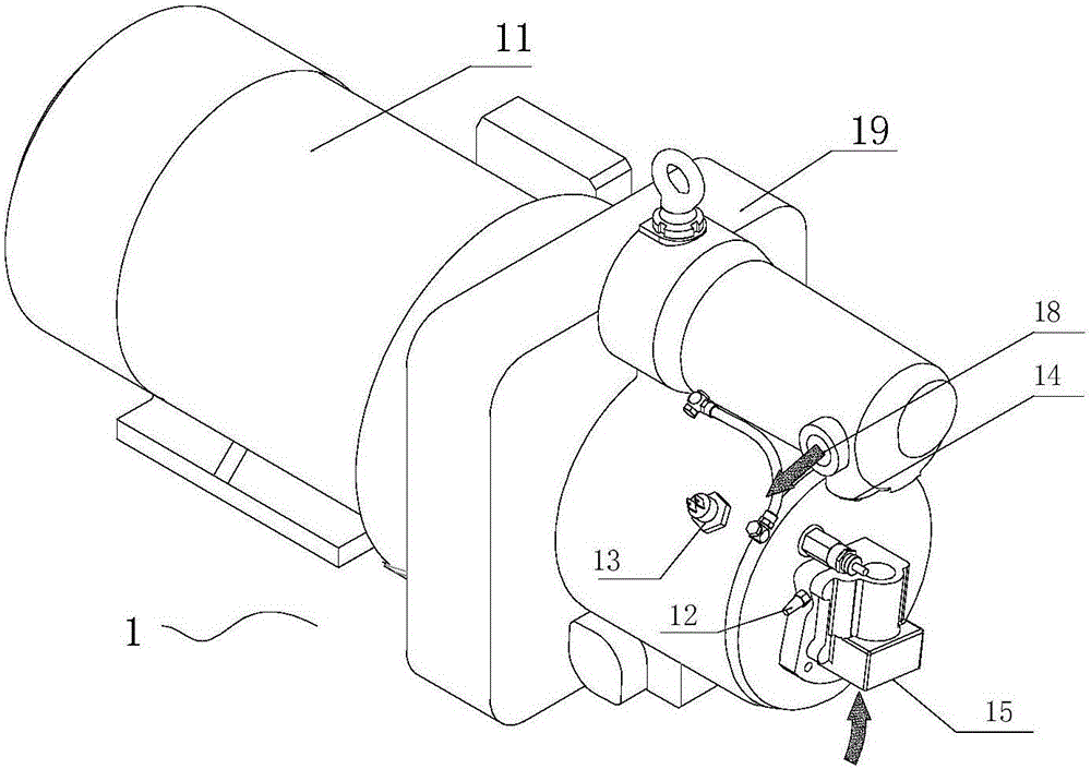
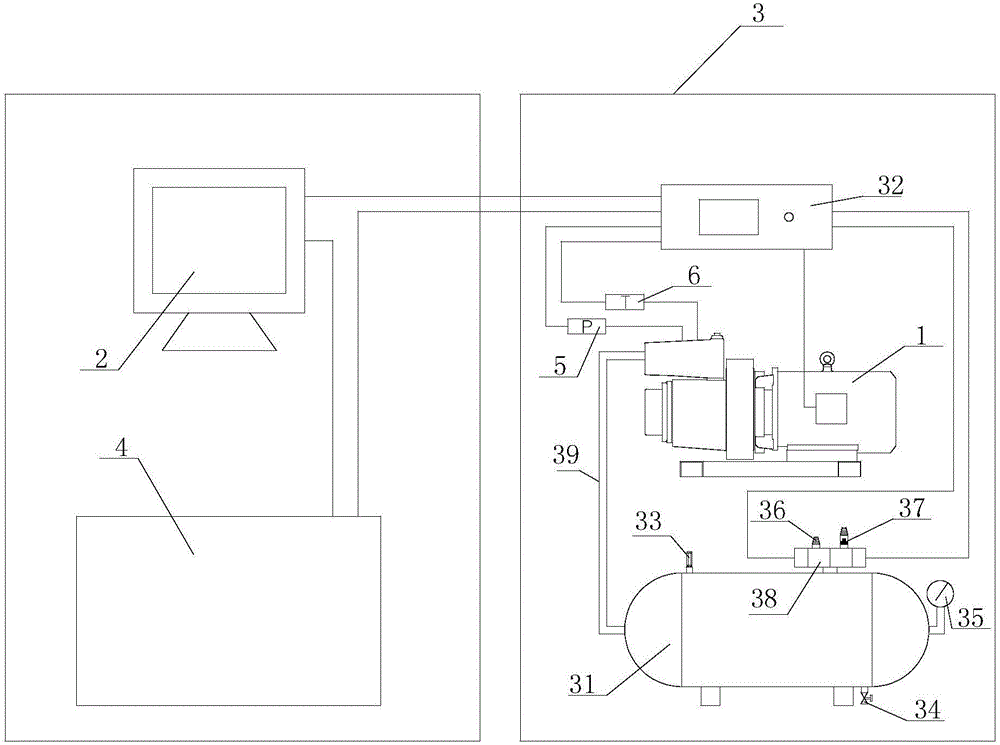
[0029] See figure 1 , figure 2 This embodiment discloses a test system for a vehicle-mounted sliding vane air compressor 1, which includes an upper computer 2 and a plurality of test units respectively connected to the upper computer 2, a plurality of test units and a plurality of test stations 3 one by one Correspondingly, each test unit includes an air storage tank 31, an operation console 32, and an air compressor 1 to be tested. The upper computer 2 and the operation console 32 are powered by the power distribution cabinet 4. One end of the operation console 32 is electrically connected with the host computer 2 and...


PUM


Abstract

The invention discloses a test system and a test method for vehicle-mounted sliding vane type air compressors. The test system comprises an upper computer and a plurality of testing units connected with the upper computer; each testing unit comprises a gas storage tank, an operation console and a to-be-tested air compressor; a temperature sensor and a pressure sensor are installed on a host of each air compressor; an air outlet of each air compressor is connected with the corresponding gas storage tank through an air outlet pipe; each gas storage tank is provided with a pressure meter and a small-hole flow measuring device; each small-hole flow measuring device comprises a silencer, a small-hole spray nozzle and an electromagnetic switching valve; each electromagnetic switching valve is electrically connected with the corresponding operation console; one end of each silencer and one end of the corresponding small-hole spray nozzle communicate with the corresponding gas storage tank through the corresponding electromagnetic switching valve; the other end of each silencer and the other end of the corresponding small-hole spray nozzle communicate with the outside world; and mutual switching between the silencers and the small-hole spray nozzles is achieved by switching the electromagnetic switching valves. The test system and the test method for the vehicle-mounted sliding vane air compressors have the beneficial effects that the function of measuring a plurality of performance parameters at multiple stations at the same time is really achieved, the testing efficiency is greatly improved, and the testing cost is reduced.

Description

Technical field [0001] The invention relates to the technical field of air compressor performance testing, in particular to a test system and a test method for a vehicle-mounted sliding vane air compressor. Background technique [0002] The air compressor (hereinafter referred to as: air compressor) includes two main components: the main engine and the drive motor. The main engine is the core component of the air compressor, which directly affects the performance of the air compressor. According to the working principle of the air compressor, the main engine structure includes intake valve, movement (mainly stator and rotor parts), minimum pressure valve, unloading valve, temperature control valve, cooling system, etc. Its main performance indicators include flow, current, temperature, Pressure, unloading time. Due to the large number of air compressor performance indicators and a certain correlation between the performance indicators, it is difficult to comprehensively determin...

Claims


Application Information

Patent Timeline
Patent Type & Authority Patents(China)
IPC IPC(8): F04B51/00
CPCF04B51/00F04C2270/86
Inventor 吴泰
Owner 吴泰
Why Eureka
Try Eureka