
Throttle valve

A throttle valve and valve seat technology, which is applied to fluid pressure actuating devices, servo motor components, mechanical equipment, etc. Possibilities, increased work stability, reduced machining and assembly accuracy requirements

Active Publication Date: 2016-10-12
OCEAN UNIV OF CHINA
View PDF6 Cites 7 Cited by
  • Summary
  • Abstract
  • Description
  • Claims
  • Application Information

AI Technical Summary

Problems solved by technology

However, the structure of this kind of throttle valve is relatively complicated, and the processing accuracy and assembly accuracy of the valve core and valve seat are relatively high, and the flow area ratio of the two-stage valve port is fixed, and the anti-cavitation performance is limited.

Method used


Image

  • Throttle valve
  • Throttle valve

Examples


Embodiment 1

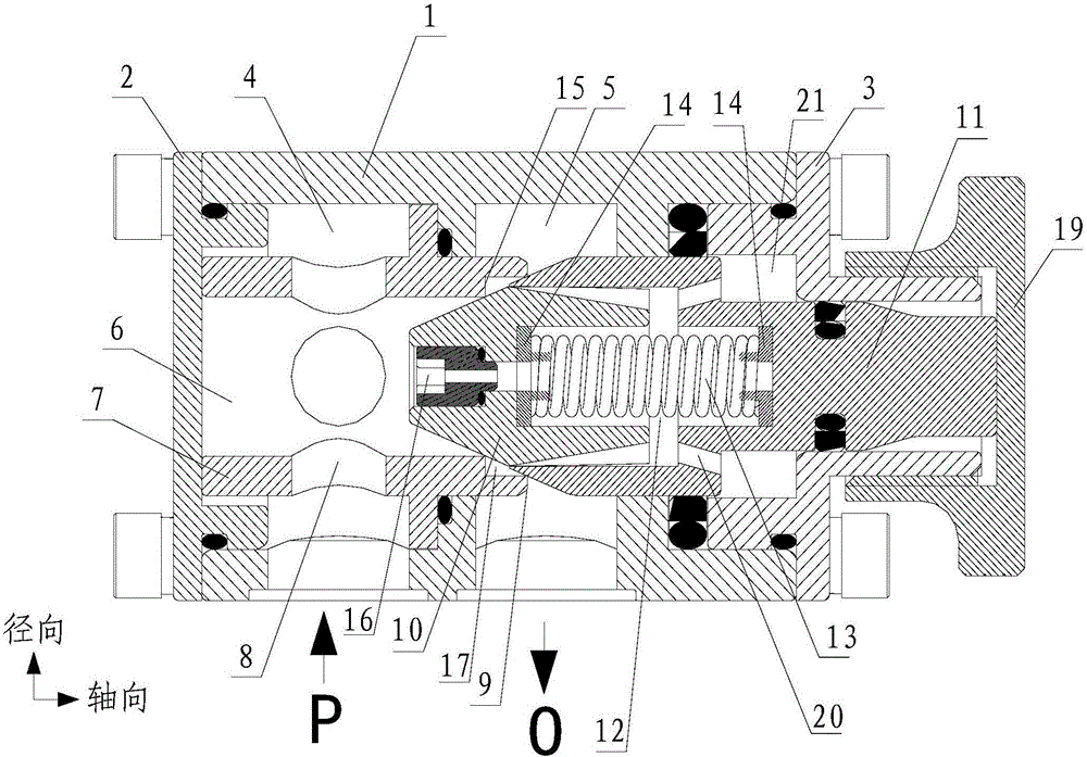
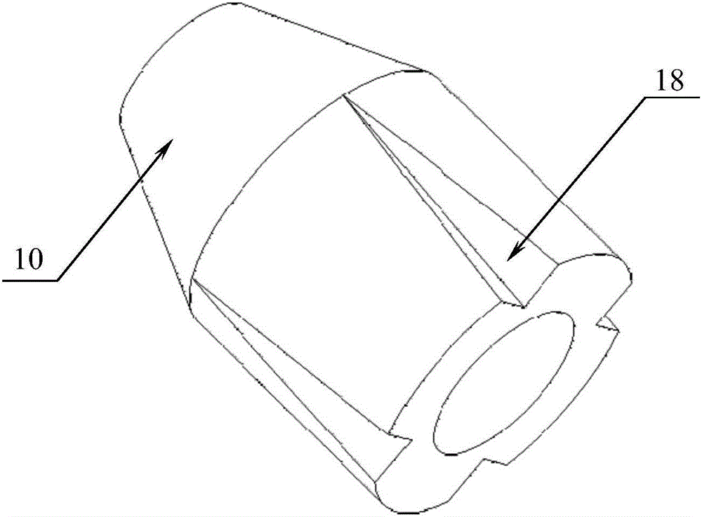
[0025] Example 1, such as figure 1 As shown, this embodiment discloses a throttle valve, including a valve body 1 with a liquid inlet P and a liquid outlet O, and the two ends of the valve body 1 are respectively provided with a left end cover 2 and a right end cover 3, as a As an alternative, in this embodiment, the left end cover 2 and the right end cover 3 are connected to the valve body 1 by bolts. The valve body 1 is also provided with a liquid inlet chamber 4 communicating with the liquid inlet P and a liquid outlet chamber 5 communicating with the liquid outlet O. A valve seat 7 with a cavity 6 is installed in the liquid inlet chamber 4, and the valve The hole 8 on the seat 7 makes the valve seat cavity 6 communicate with the liquid inlet chamber 4. As an alternative, there are four holes 8 on the valve seat 7 in this embodiment, and each hole 8 is along the valve seat. The radial directions of 7 are distributed in a cross. The valve port of the valve seat 7 is a two-...


PUM


Abstract

The invention discloses a throttle valve. The throttle valve comprises a valve body with a liquid inlet and a liquid outlet, a left end cap and a right end cap are arranged at the two ends of the valve body respectively, the valve body is internally provided with a liquid inlet chamber communicated with the liquid inlet and a liquid outlet chamber communicated with the liquid outlet, and a valve port of a valve seat is of a two-stage step structure; the liquid outlet chamber is internally provided with an internal valve element and an external valve element which are each provided with an inner hole, the two inner holes are formed oppositely to form a middle cavity which is internally provided with a spring, and the two ends of the spring are connected with the internal valve element and the external valve element through spring seats respectively. According to the throttle valve, the valve port of the valve seat is of the two-stage step structure, when liquid pressure is small and cannot overcome an elastic force of the spring, a first-stage throttle orifice is closed, the throttle valve is equivalent to a first-stage throttle valve, when the liquid pressure exceeds the elastic force of the spring, the internal valve element slides in the direction from the inner hole of the external valve element to the external valve element, the first-stage throttle orifice is opened, a second-stage throttle orifice starts to work, and the throttle valve becomes the second throttle valve.

Description

technical field [0001] The invention belongs to the field of flow control elements in hydraulic systems, in particular to a throttle valve in the field. Background technique [0002] Throttle valve is a valve that controls fluid flow by changing the throttle area or throttle length, and is a commonly used flow control component in hydraulic systems. Used together with the electromagnetic unloading overflow valve, it can realize the functions of loading and unloading the pump and regulating the speed of the system. When working, close the throttle valve, and adjust the electromagnetic overflow valve to make the hydraulic pump work under the rated working condition. Then adjust the throttle valve to make the hydraulic pump work at a certain pressure. [0003] Ordinary single-stage throttle valve has no flow negative feedback function. When the spool position is constant, the passing flow is only related to the pressure difference at both ends of the valve port, and cannot co...

Claims


Application Information

Patent Timeline
Patent Type & Authority Applications(China)
IPC IPC(8): F15B13/02
CPCF15B13/02
Inventor 杨友胜刘冬婷毛燕语邢世琦
Owner OCEAN UNIV OF CHINA
Learn More