Low-energy electromagnetic valve control method and device

A technology for control devices and solenoid valves, applied to valve devices, valve operation/release devices, valve details, etc., can solve problems such as increased power consumption, short life, easy-to-burn electromagnetic coils, etc., to achieve reduced temperature rise, Effects of extended life and reduced operating power consumption

Active Publication Date: 2016-10-12
GUANGZHOU CITY DONG BA ENERGY TECH
View PDF7 Cites 5 Cited by
  • Summary
  • Abstract
  • Description
  • Claims
  • Application Information

AI Technical Summary

Problems solved by technology

[0002] The magnetic valves used in commercial furnaces are directly rectified and driven by a voltage greater than or equal to the rated driving voltage of the solenoid valve. The power consumption is large and the temperature rises. It is easy to burn the electromagnetic coil in a high temperature environment for a long time, and the service life is short.

Method used


Image

  • Low-energy electromagnetic valve control method and device

Examples


Embodiment 1

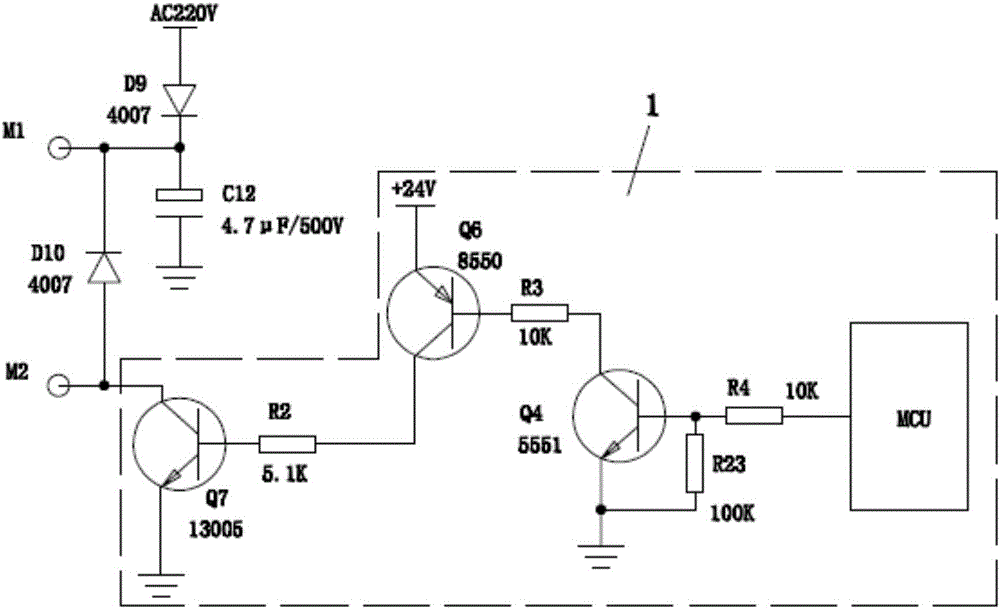
[0018] The specific embodiment of the present invention is as figure 1 As shown, a low energy consumption solenoid valve control device includes solenoid valve control output terminals M1 and M2 for controlling the solenoid valve. It also includes a composite drive circuit 1, the composite drive circuit 1 includes a control chip MCU, a resistor R4, a transistor Q4, a resistor R3, a transistor Q6, a resistor R2 and a transistor Q7 connected in sequence, the base of the transistor Q4 and its emitter are connected with a Resistor R23. The transistor Q7 is connected with the solenoid valve control output terminals M1 and M2. The control chip MCU can output a strong suction signal or a PWM pulse width modulation signal according to whether the solenoid valve is open or not. The strong suction signal can make the transistor Q7 drive the solenoid valve control output terminals M1 and M2 to output a current greater than or equal to the rated drive current value of the solenoid valve...


PUM


Abstract

The invention discloses a low-energy electromagnetic valve control device which comprises an electromagnetic valve control output terminal M1, an electromagnetic valve control output terminal M2 and a compound driving circuit connected with the electromagnetic valve control output terminal M1 and the electromagnetic valve control output terminal M2. The invention further discloses a low-energy electromagnetic valve control method which comprises the following steps: the compound driving circuit enables the electromagnetic valve control output terminal M1 and the electromagnetic valve control output terminal M2 to output electric current of which the value is greater than or equal to the rated drive current value of an electromagnetic valve, and the electromagnetic valve is opened with strong energy; after the electromagnetic valve is opened, the compound driving circuit enables the electromagnetic valve control output terminal M1 and the electromagnetic valve control output terminal M2 to output electric current which can at least keep reliable absorption of the electromagnetic valve, so as to ensure that the electromagnetic valve is maintained in the open state. According to the low-energy electromagnetic valve control method and device, the energy consumption of the electromagnetic valve is reduced, heat generated by a coil in the electromagnetic valve is reduced, and meanwhile quick closing of the electromagnetic valve is facilitated, so that the purposes of saving energy, reducing temperature and prolonging the service life of the electromagnetic valve are achieved.

Description

technical field [0001] The invention relates to the field of commercial stoves, in particular to a method and device for controlling a low energy consumption electromagnetic valve. Background technique [0002] The solenoid valves used in commercial furnaces are directly rectified and driven by a voltage greater than or equal to the rated driving voltage of the solenoid valve. The power consumption is large and the temperature rises. It is easy to burn the solenoid coil in a high temperature environment for a long time, and the service life is short. Contents of the invention [0003] The purpose of the present invention is to provide a low energy consumption solenoid valve control method and device, in order to reduce the energy consumption of the solenoid valve, reduce the heating of the coil in the solenoid valve, and at the same time facilitate the rapid closing of the solenoid valve, so as to achieve energy saving and cooling, increase the electromagnetic purpose of v...

Claims


Application Information

Patent Timeline
Patent Type & Authority Applications(China)
IPC IPC(8): F16K31/06
CPCF16K31/0675
Inventor 冯成威
Owner GUANGZHOU CITY DONG BA ENERGY TECH
Why Eureka
Try Eureka