Lifting type image collection system for intelligent traffic violation information collection
A technology for information collection and intelligent transportation, applied in the field of intelligent transportation, can solve the problems of complicated installation and disassembly of cameras, complicated structure of camera mounting frame, etc., to achieve the effect of easy installation or disassembly
- Summary
- Abstract
- Description
- Claims
- Application Information
AI Technical Summary
Problems solved by technology
Method used
Image
Examples
Embodiment 1
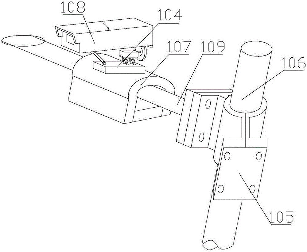
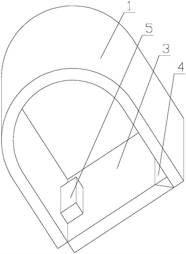
[0056] An elevating image acquisition system for intelligent traffic violation information collection, comprising a land rod 106, a cross bar 109 is connected to the land rod 106 through a hoop-type connecting frame 105, and a mounting frame 107 is arranged on the cross rod 109, A camera 108 is installed above the mounting frame 107 through a lifting base 104; the mounting frame 107 includes a U-shaped connector 1, and the outer surface of the arc section of the U-shaped connector 1 is connected to the camera 108. The rod 109 is located in the inner U-shaped groove of the U-shaped connector 1, the bottom of the connecting end of the U-shaped connector 1 is connected with a connecting inclined block 4, and the inclined plane of the connecting inclined block 4 is connected to the center line of the connecting inclined block 4. The included angle is 45°, the inclined surface of the connecting inclined block 4 is connected with the connecting sealing plate 3 through the ball head 2...
Embodiment 2
[0058] On the basis of Embodiment 1, the locking part 5 includes a lock body 51, the front of the lock body 51 is provided with a semicircular groove transversely, and the back of the lock body 51 is longitudinally provided with a semicircular groove, so The front and back of the lock body 51 are hinged with buckles 52 and locking levers 531 through the hinge shaft 54, and the buckles 52 and locking levers 531 are located at the left and right sides of the semicircular groove of the lock body 51. Side; the buckle 52 is provided with a semicircular groove, the semicircular groove on the buckle 52 and the semicircular groove on the front and back of the lock body 51 form a card hole 511; the locking rod 531 A locking knob 53 is connected to the end of the locking rod 531 , and the locking rod 531 can be located in the groove on the end surface of the buckle 52 and snapped and locked with the lock body 51 through the locking knob 53 .
Embodiment 3
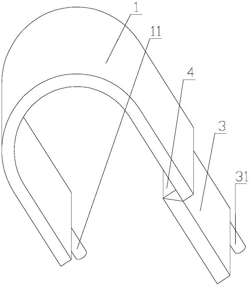
[0060] On the basis of the second embodiment, the bottom of the locking end of the U-shaped connector 1 is connected to the first locking column 11, and the bottom of the locking end of the connecting sealing plate 3 is connected to the second locking column 31, so The first locking post 11 and the second locking post 31 are respectively located in the locking holes 511 on the front side and back side of the lock body 51 .
PUM
 Abstract
Description
Claims
Application Information
 - R&D
- Intellectual Property
- Life Sciences
- Materials
- Tech Scout
- Unparalleled Data Quality
- Higher Quality Content
- 60% Fewer Hallucinations
Browse by: Latest US Patents, China's latest patents, Technical Efficacy Thesaurus, Application Domain, Technology Topic, Popular Technical Reports.
© 2025 PatSnap. All rights reserved.Legal|Privacy policy|Modern Slavery Act Transparency Statement|Sitemap|About US| Contact US: help@patsnap.com


