Safe state tracking detection method and device

A security status, tracking and detection technology, applied in measurement devices, surveying and navigation, radio wave measurement systems, etc., can solve problems such as difficult and short-distance mobile security status tracking and detection, and achieve improved experience, accurate direction, and easy countermeasures. Effect

Inactive Publication Date: 2016-10-12
BEIJING QIHOO TECH CO LTD +1
5 Cites 3 Cited by

AI-Extracted Technical Summary

Problems solved by technology

[0010] Aiming at the shortcomings of the existing methods, the present invention proposes a method and device for tracking and detecti...

Method used

And, in the embodiment of the present invention, utilize the geomagnetic direction of real-time acquisition to correct the direction of moving track, make the direction of moving track more accurate, provide more accurate moving track for user's reference in the mode of showing, have It helps the user to more accurately judge whether the wearer of the smart wearable device is in an unsafe state based on a more precise movement trajectory, and further improves the user experience.
It is easy to understand that based on the above analysis, the accuracy of the geographic coordinates collected by the GPS receiver in the embodiment of the present invention is relatively low, and the error range of the geographic coordinates may be less than the size of the moving track, or belong to the same order of magnitude as the size of the moving track Therefore, based on the geographic location information of the mobile trajectory determined based on the geographic coordinates collected by the GPS receiver, the direction of the mobile trajectory determined according to the geographic location information of multiple trajectory points usually has a large error. However, according to the high accuracy of the geomagnetic direction collected by the geomagnetic sensor, the direction of the moving track can be corrected, so that the direction of the generated moving track is...

Abstract

The embodiment of the invention provides a safe state tracking detection method and device. The method comprises the steps of acquiring the acceleration magnitude and geographical coordinates of intelligent wearing equipment in real time; determining whether the equipment is in an unsafe area according to the geographical coordinates acquired corresponding to the acceleration magnitude after it is detected that the acquired acceleration magnitude exceeds a preset acceleration threshold value; generating an unsafe state message and sending the unsafe state message to a corresponding terminal unit if the equipment is in an unsafe area, so that the terminal unit conducts displaying according to the unsafe state message. According to the method and device, the safe state of a wearer are tracked based on the acceleration magnitude and geographical coordinates acquired in real time; the fact that the wearer is in the unsafe state is detected in real time according to the acquired acceleration magnitude exceeding the preset acceleration threshold value and the geographical coordinates of the unsafe area, the unsafe state message is generated and sent to the corresponding terminal unit, and a user of the terminal unit is reminded in time that the wearer is likely to be in an unsafe state, so that the user can take measures in time.

Application Domain

Navigation by speed/acceleration measurementsSatellite radio beaconing

Technology Topic

Real time acquisitionCountermeasure +5

Image

  • Safe state tracking detection method and device
  • Safe state tracking detection method and device
  • Safe state tracking detection method and device

Examples

  • Experimental program(1)

Example Embodiment

[0066] The embodiments of the present invention are described in detail below. Examples of the embodiments are shown in the accompanying drawings, in which the same or similar reference numerals indicate the same or similar elements or elements with the same or similar functions. The embodiments described below with reference to the accompanying drawings are exemplary, and are only used to explain the present invention, and cannot be construed as limiting the present invention.
[0067] Those skilled in the art can understand that, unless specifically stated, the singular forms "a", "an", "said" and "the" used herein may also include plural forms. It should be further understood that the term "comprising" used in the specification of the present invention refers to the presence of the described features, integers, steps, operations, elements and/or components, but does not exclude the presence or addition of one or more other features, Integers, steps, operations, elements, components, and/or groups thereof. It should be understood that when we refer to an element as being "connected" or "coupled" to another element, it can be directly connected or coupled to the other element, or intervening elements may also be present. In addition, “connected” or “coupled” used herein may include wireless connection or wireless coupling. The term "and/or" used herein includes all or any unit and all combinations of one or more associated listed items.
[0068] Those skilled in the art can understand that, unless otherwise defined, all terms (including technical and scientific terms) used herein have the same meanings as those commonly understood by those of ordinary skill in the art to which the present invention belongs. It should also be understood that terms such as those defined in general dictionaries should be understood to have a meaning consistent with the meaning in the context of the prior art, and unless specifically defined as here, they will not be idealized or overly Explain the formal meaning.
[0069] Those skilled in the art can understand that the term "terminal" and "terminal equipment" used herein include both wireless signal receiver equipment, equipment that only has wireless signal receivers without transmitting capability, and equipment receiving and transmitting hardware. A device that has a device capable of receiving and transmitting hardware for two-way communication on a two-way communication link. Such equipment may include: cellular or other communication equipment, which has a single-line display or multi-line display or cellular or other communication equipment without a multi-line display; PCS (Personal Communications Service, personal communication system), which can combine voice and data Processing, fax and/or data communication capabilities; PDA (Personal Digital Assistant), which may include radio frequency receivers, pagers, Internet/Intranet access, web browsers, notepads, calendars and/or GPS (Global Positioning System) , Global Positioning System) receiver; conventional laptop and/or palmtop computer or other equipment, which has and/or includes a radio frequency receiver, conventional laptop and/or palmtop computer or other equipment. The "terminal" and "terminal equipment" used here may be portable, transportable, installed in vehicles (aviation, sea and/or land), or suitable and/or configured to operate locally, and/or In a distributed form, it runs on the earth and/or any other location in space. The "terminal" and "terminal device" used here can also be communication terminals, internet terminals, music/video playback terminals, for example, PDAs, MIDs (Mobile Internet Devices) and/or music/video playback Functional mobile phones can also be devices such as smart TVs and set-top boxes.
[0070] The inventors of the present invention have discovered through research that when the wearer is walking, running, etc., the acceleration value collected by the smart wearable device is usually small; even if the wearer is riding in a high-speed transportation such as high-speed rail or airplane, Since vehicles generally accelerate slowly, the acceleration value collected by the wearer's smart wearable device is usually not large. When an impact event such as a car accident occurs, the acceleration collected by the smart wearable device is usually large, for example, reaching or exceeding the acceleration of gravity.
[0071] Based on the above findings, in the embodiment of the present invention, the acceleration value and geographic coordinates of the smart wearable device are collected in real time; after detecting that the collected acceleration value exceeds the preset acceleration threshold, it is determined whether the current acceleration value is collected according to the geographic coordinates corresponding to the acceleration value. It is in an unsafe area; if it is currently in an unsafe area, unsafe state information is generated, and the unsafe state information is sent to the corresponding terminal device, so that the terminal device displays the unsafe state information. It can be seen that, in the embodiment of the present invention, the smart wearable device tracks the wearer's security status in real time by tracking the acceleration value and geographic coordinates it collects in real time; the accuracy of the collected geographic coordinates is sufficient to determine where the smart wearable device is currently located Whether the area (equivalent to the area where the wearer is currently located) is a safe area or an unsafe area. Therefore, according to the acceleration value exceeding the threshold and the geographical coordinates of the unsafe area, the wearer can be detected in real time in an unsafe state, and unsafe information can be generated and sent to the corresponding terminal device, thereby promptly reminding the user of the terminal device to the wearer It is likely to be in an unsafe state, which is convenient for users of terminal devices to deal with timely countermeasures, and can avoid regrets caused by information delays, thereby improving user experience.
[0072] The technical solutions of the embodiments of the present invention will be described in detail below with reference to the drawings.
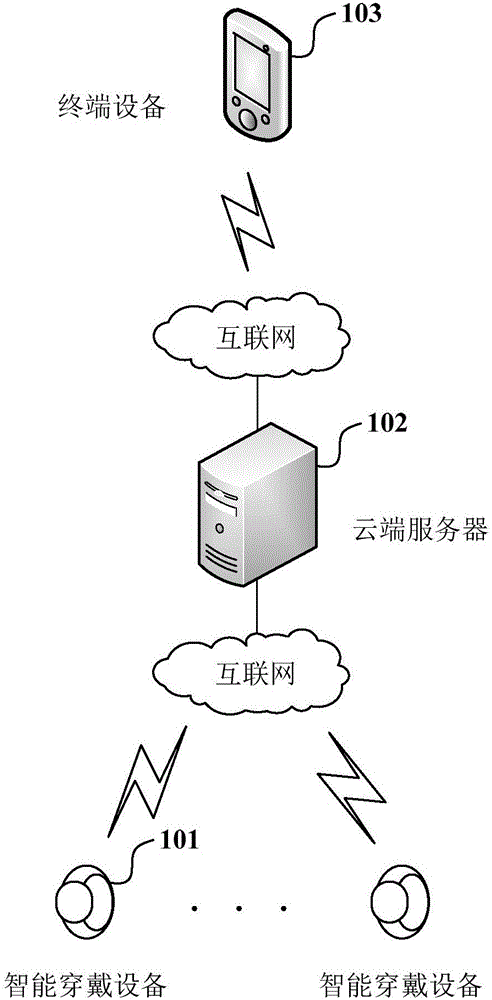
[0073] The schematic diagram of the architecture of the security state tracking detection system of the embodiment of the present invention is as follows: figure 1 As shown, it includes: a smart wearable device 101, a cloud server 102, and a terminal device 103.
[0074] Among them, there may be multiple smart wearable devices 101; smart wearable devices 101 may specifically be one of the following devices: smart watches, smart bracelets, smart glasses, smart clothing, etc. The smart wearable device 101 is usually provided with a mobile communication card; for example, a SIM (Subscriber Identity Module) card, a nano-SIM card or a micro-SIM card, etc. A communication number is stored in the mobile communication card, and the communication number is used as the communication number of the smart wearable device 101. The smart wearable device 101 is provided with a WiFi module.
[0075] The smart wearable device 101 can access the network in a wireless manner. For example, the smart wearable device 101 accesses the Internet through one of the following methods: GPRS (General Packet Radio Service) network, 3G (3rd-Generation wireless telephone technology) network, LTE (General Packet Radio Service) Long Term Evolution (Long Term Evolution) network.
[0076] The smart wearable device 101 is provided with a satellite signal receiver and a G-sensor.
[0077] The satellite signal receiver may include at least one of the following: a GPS receiver and a Beidou satellite signal receiver.
[0078] G-sensor (Gravity-sensor, acceleration sensor for short) can perceive the change of acceleration force. The acceleration force is the force acting on the object when the mass of the object in the G-sensor is accelerating, such as The force exerted on the object by various movement changes such as shaking, falling, rising, and falling can be converted into electrical signals by the G-sensor, and then the acceleration is converted according to Newton's second law.
[0079] Those skilled in the art can understand that although the G-sensor is called a gravity acceleration sensor in its name, in fact, according to different shaft designs, it can detect acceleration in multiple directions including the direction of gravity. For example, a three-axis G-sensor can detect acceleration in three directions.
[0080] Preferably, the smart wearable device 101 is provided with a gyroscope.
[0081] A gyroscope is usually an angular motion detection device that uses the moment of momentum sensitive shell of a high-speed rotating body to rotate one or two axes orthogonal to the rotation axis relative to the inertial space. It is often used to detect the angular velocity.
[0082] Preferably, the smart wearable device 101 is provided with a geomagnetic sensor.
[0083] The geomagnetic sensor is a type of information that uses the different motion states of the measured object (that is, the smart wearable device 101 in the embodiment of the present invention) in the geomagnetic field to indicate the posture and motion angle of the measured object by sensing the changes in the distribution of the geomagnetic field Measuring device. In the embodiment of the present invention, the geomagnetic sensor in the smart wearable device 101 is used to detect the direction of movement of the smart wearable device 101 in the geomagnetic field, referred to as the geomagnetic direction for short.
[0084] The cloud server 102 is wired to the network. For example, the cloud server 102 accesses the wide area network or backbone network in the Internet through optical fiber.
[0085] The cloud server 102 is used to bind the corresponding smart wearable device 101 and the terminal device 103, forward the instructions sent by the terminal device 103 to the smart wearable device 101, and forward the information collected and uploaded by the smart wearable device 101 to the terminal device 103, etc. , The specific functions will be detailed later, so I won’t repeat them here.
[0086] The terminal device 103 may be multiple; the terminal device 103 may be a terminal device such as a smart phone or a tablet computer that can talk to. The characteristic information of the terminal device 103 may include: the ID and communication number of the terminal device. Specifically, the terminal device is configured with a mobile communication card, such as a SIM card, which has a communication number; and the terminal device has an ID of the terminal device, such as IMEI (International Mobile Equipment Identity, mobile equipment international identity code).
[0087] Before the smart wearable device 101 is activated (for example, before leaving the factory), the cloud server 102 of the service party usually associates the unique identification (for example, a universal unique identifier) ​​of the smart wearable device 101 with the The characteristic information of the smart wearable device 101 is correspondingly stored. The feature information of the smart wearable device 101 may be the communication number of the smart wearable device 101 or the unique feature machine identification code of the smart wearable device 101.
[0088] Before the security status of the smart wearable device 101 is tracked and detected, the terminal device 103 logs in to the cloud server 102 of the service party to register a user account; the cloud server 103 activates the user account, and registers the characteristic information of the terminal device 103 with the terminal device 103 The user account is bound. After the terminal device 103 uploads the feature information of the terminal device and the identification of the smart wearable device 101 to the cloud server 102, the cloud server 102 confirms that the smart wearable device 101 that received the identification is activated, and compares the identification and feature information of the smart wearable device 101 with The user account registered by the terminal device 103 is bound.
[0089] It can be understood that, for each user account in the cloud server 102, the identification and feature information of several smart wearable devices 101 and the feature information of several terminal devices 103 can be bound to the user account name.
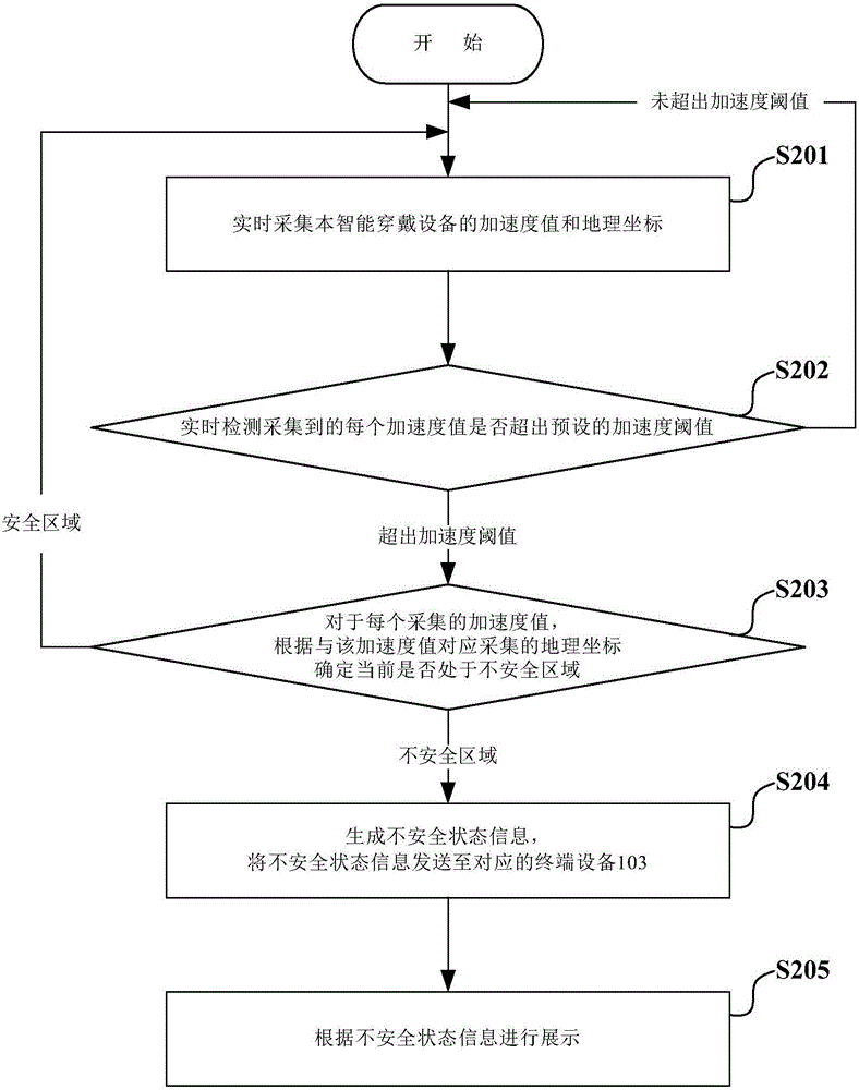
[0090] The following describes a method for tracking and detecting a security state provided by an embodiment of the present invention. The flow diagram of the method is as follows: figure 2 As shown, including the following steps:
[0091] S201: Collect the acceleration value and geographic coordinates of the smart wearable device in real time.
[0092] The smart wearable device 101 collects real-time acceleration values ​​through its internal G-sensor as the real-time acceleration value of the smart wearable device; and collects geographic coordinates in real time through the satellite signal receiver inside the smart wearable device as the real-time collection The geographic coordinates of the smart wearable device. The specific collection methods of acceleration values ​​and geographic coordinates are well known to those skilled in the art, and will not be repeated here. The satellite signal receiver may be at least one of the following: GPS receiver, Beidou satellite signal receiver.
[0093] G-sensor can perceive the change of acceleration force. The acceleration force is the force acting on the object when the mass of the object in the G-sensor is accelerated, such as shaking, falling, rising, falling, etc. The force on the object can be converted into an electrical signal by the G-sensor, and then the acceleration is converted according to Newton's second law.
[0094] Those skilled in the art can understand that the G-sensor can detect acceleration in multiple directions including the direction of gravity according to different shaft designs. For example, the three-axis G-sensor can detect the acceleration of the smart wearable device 101 in the three directions of the X-axis and Y-axis in the plane and the Z-axis perpendicular to the plane in the solid rectangular coordinate system.
[0095] Preferably, the smart wearable device 101 collects real-time angular velocity through its internal gyroscope while collecting the acceleration value and geographic coordinates in real time, as the real-time collected angular velocity of the smart wearable device.
[0096] A gyroscope is usually an angular motion detection device that uses the moment of momentum sensitive shell of a high-speed rotating body to rotate one or two axes orthogonal to the rotation axis relative to the inertial space. It is often used to detect the angular velocity.
[0097] Further, the gyroscope in the embodiment of the present invention can detect angular velocities in multiple planes. For example, the angular velocity of the smart wearable device 101 in the horizontal plane and/or the vertical plane can be detected.
[0098] Preferably, while the smart wearable device 101 collects acceleration values ​​and geographic coordinates in real time, it collects the geomagnetic direction in real time through its internal geomagnetic sensor as the real-time collected geomagnetic direction of the smart wearable device.
[0099] The geomagnetic sensor is a kind of measuring device that uses the different motion states of the measured object in the geomagnetic field to indicate the posture and movement angle of the measured object by sensing the changes in the distribution of the geomagnetic field. In the embodiment of the present invention, the geomagnetic sensor in the smart wearable device 101 is used to detect the direction of movement of the smart wearable device 101 in the geomagnetic field, referred to as the geomagnetic direction for short.
[0100] S202: Detect in real time whether each collected acceleration value exceeds a preset acceleration threshold; after detecting that the acceleration value exceeds the acceleration threshold, execute step S203; after detecting that the acceleration value does not exceed the acceleration threshold, execute step S201.
[0101] For each acceleration value collected in real time, the smart wearable device 101 compares the acceleration value with a preset acceleration threshold, and detects whether the acceleration value is greater than the acceleration threshold; if it is, it detects that the acceleration value exceeds the acceleration threshold, then execute Step S203: If not, that is, it is detected that the acceleration value does not exceed the acceleration threshold, go to step S201.
[0102] Those skilled in the art can set the acceleration threshold according to experimental data, historical data, empirical data, and/or actual conditions. The embodiment of the present invention does not limit this, and the specific setting method is a conventional technical means in the field, and will not be repeated here. .
[0103] Preferably, when the smart wearable device 201 detects that the acceleration value does not exceed the acceleration threshold, it ignores the acceleration value and the corresponding collected geographic coordinates, and then executes step S201.
[0104] Those skilled in the art can understand that the acceleration threshold is set reasonably. When the collected acceleration value of the smart wearable device 101 exceeds the acceleration threshold, it can generally be considered that the acceleration value of the wearer's movement of the smart wearable device 101 exceeds the normal range (or The scope of historical monitoring), the wearer of the smart wearable device 101 is likely to encounter an abnormal situation and is in an unsafe state.
[0105] S203: For each collected acceleration value, determine whether it is currently in an unsafe area according to the geographic coordinates collected corresponding to the acceleration value; if it is currently in an unsafe area, perform step S204; if it is currently in a safe area, perform step S201 .
[0106] Specifically, for each collected acceleration value, the smart wearable device 101 determines whether the geographic coordinates match the coordinate range of the unsafe area in the pre-stored electronic map for the geographic coordinates collected corresponding to the acceleration value.
[0107] If it is determined according to the matching result that the smart wearable device 101 and its wearer are currently in an unsafe area, step S204 is executed; if it is determined according to the matching result that the smart wearable device 101 and its wearer are currently in a safe area, then step S201 is executed.
[0108] Unsafe areas include at least one of the following: traffic roads, parking lots, bridges, and water bodies. Traffic roads may include at least one of the following: highways, railways, etc.; water bodies may include at least one of the following: rivers, rivers, lakes, seas, ponds, and the like. Preferably, those skilled in the art can set the unsafe area and its coordinate range according to actual needs.
[0109] The safe area is the area except the unsafe area in the electronic map.
[0110] Preferably, when the geographic coordinates collected by the smart wearable device 101 belong to the coordinate range of the unsafe area, it is determined that the geographic coordinates match the coordinate range of the unsafe area in the electronic map, and the smart wearable device 101 and its wearer are currently in Unsafe area.
[0111] Preferably, when the distance between the geographic coordinates collected by the smart wearable device 101 and any coordinate in the coordinate range of the unsafe area is less than the preset distance threshold, the geographic coordinates and the coordinate range of the unsafe area in the electronic map are determined Matching, the smart wearable device 101 and its wearer are currently in an unsafe area.
[0112] S204: Generate unsafe state information, and send the unsafe state information to the corresponding terminal device 103.
[0113] The smart wearable device 101 generates the movement trajectory of the smart wearable device in this step according to the acceleration values ​​collected at multiple times. The method of generating the movement trajectory of an object according to the acceleration values ​​of the object at multiple times is well known to those skilled in the art, and will not be repeated here.
[0114] Preferably, the smart wearable device 101 generates the movement trajectory of the smart wearable device in this step according to the acceleration values ​​and angular velocities collected at multiple times. The specific generation method is well known to those skilled in the art, and will not be repeated here.
[0115] Through the analysis in the foregoing steps, it can be known that the smart wearable device 101 can collect acceleration values ​​in multiple directions and angular velocities in multiple planes at each time; therefore, the generated movement trajectory can be a three-dimensional movement trajectory. The three-dimensional movement track includes the movement track of the plane (for example, the movement track on the road). Each track point on the movement track corresponds to a moment.
[0116] Further, the smart wearable device 101 determines the geographic location information of the generated movement track in the electronic map. Specifically, according to the geographic coordinates corresponding to any track point in the generated movement track, the geographic location information of the geographic coordinates in the electronic map can be determined as the geographic location information of the movement track in the electronic map. The direction of the movement track can be determined according to the geographic location information of multiple track points in the movement track.
[0117] Those skilled in the art can understand that the size of the movement track of the smart wearable device 101 and its wearer in the embodiment of the present invention is usually only a few decimeters, a few meters or more than ten meters; the accuracy of the signals authorized by GPS for civil geolocation is limited, that is, the In the embodiment of the invention, the accuracy of the geographic coordinates collected by the GPS receiver is low, and the error range of the geographic coordinates may be smaller than the size of the movement track, or be of the same order of magnitude as the size of the movement track; therefore, multiple track points in the movement track correspond to Geographic coordinates may correspond to the same geographic coordinates, and geographic coordinates are mainly used for rough geographic positioning.
[0118] Preferably, the smart wearable device 101 corrects the direction of the movement track according to the geomagnetic direction collected in the time period corresponding to the movement track. Specifically, for the acceleration value corresponding to each trajectory point in the movement trajectory, the smart wearable device 101 corrects the direction of the movement trajectory according to the collected geomagnetic direction corresponding to the time when the acceleration value corresponding to each trajectory point is collected.
[0119] It is easy to understand that based on the above analysis, the accuracy of the geographic coordinates collected by the GPS receiver in the embodiment of the present invention is low, and the error range of the geographic coordinates may be smaller than the size of the movement track, or be of the same order of magnitude as the size of the movement track; therefore, The geographic location information of the moving track determined based on the geographic coordinates collected by the GPS receiver, and the direction of the moving track determined based on the geographic location information of multiple track points usually have a relatively large error. According to the geomagnetic direction collected by the geomagnetic sensor, the accuracy of the geomagnetic direction is high, and the direction of the movement track can be corrected, so that the direction of the generated movement track is more accurate.
[0120] The smart wearable device 101 sends the generated movement track and/or the determined geographic location information of the movement track to the corresponding terminal device 103.
[0121] For example, the smart wearable device 101 may send the generated movement trajectory and/or the determined geographic location information of the movement trajectory to the cloud server 102 through the 3G network, and the cloud server 102 forwards the generated movement track to the corresponding terminal device 103.
[0122] For another example, the smart wearable device 101 may send the generated movement track and/or the determined geographic location information of the movement track to the corresponding terminal device 103 located in the same WiFi network via the WiFi network.
[0123] Further, when the smart wearable device 101 sends the generated movement trajectory and/or the determined geographic location information of the movement trajectory, the acceleration value related to the movement trajectory that exceeds the acceleration threshold and/or the speed value based on the acceleration value, Send to the corresponding terminal device 103.
[0124] More preferably, the smart wearable device 101 determines the visual element corresponding to the acceleration value that exceeds the acceleration threshold involved in the generated movement track; and sends the determined visual element to the corresponding terminal device 103. The visual element may include at least one of the following: the color of the movement track, the background color, and the display mode.
[0125] S205: Display in the mobile terminal according to the unsafe state information.
[0126] The terminal device 103 dynamically demonstrates the received movement track.
[0127] Preferably, the terminal device 103 displays an electronic map in the mobile terminal corresponding to the movement track, and displays the geographic location information of the movement track in the electronic map.
[0128] For example, the terminal device 103 shows that the geographic location of the movement track is located on the side of a highway, and the dynamic demonstration of the movement track shows that the moving speed of the smart wearable device 101 and its wearer in the horizontal plane suddenly increases, and the direction also changes sharply (the angular velocity is higher). Great), which can help the user (usually the guardian of the wearer of the smart wearable device 101) to determine that the wearer may have been hit by a vehicle. Measures such as contacting the emergency center for rescue, contacting relatives and friends for help, and calling the police should be implemented immediately. Protect the life safety and health of the wearer as much as possible, thereby enhancing the user experience.
[0129] For another example, the geographic location where the terminal device 103 displays the movement track is located in a bridge on the river, and the dynamic demonstration of the movement track indicates that the smart wearable device 101 and its wearer have undergone a parabolic movement perpendicular to the horizontal plane or a straight decline and falling The speed is getting faster and faster, which can help users determine that the wearer may have fallen into the water. Measures such as contacting the emergency center for rescue, contacting people near the incident site for assistance, and reporting to the police should be implemented immediately to protect the wearer as much as possible. Life safety and health, thereby enhancing the user experience.
[0130] Preferably, the terminal device 103 displays the received acceleration value and/or speed value and the received movement track correspondingly. Specifically, in the process of dynamically demonstrating the movement trajectory, the terminal device 103 corresponds to each trajectory point in the movement trajectory and displays the acceleration value and/or velocity value at the time when the trajectory point is located.
[0131] More preferably, the terminal device 103 displays the received visual elements. The visual elements may include at least one of the following: the color of the movement track, the background color, and the display mode.
[0132] Further, displaying the visual elements includes performing at least one of the following: coloring, flashing, floating, and highlighting the movement track.
[0133] For example, if the visual element received by the terminal device 103 is specifically red as the color of the movement trajectory, the movement trajectory is rendered in red for display to remind the user of the terminal device 103 that the wearer of the smart wearable device 101 may be insecure Status, which is convenient for users to take countermeasures in time.
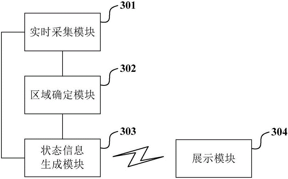
[0134] Based on the above-mentioned safe state tracking and detection method, an embodiment of the present invention also provides a safe state tracking and detection device. The internal structure of the device is shown as image 3 As shown, it includes: a real-time collection module 301, an area determination module 302, a status information generation module 303, and a display module 304.
[0135] Among them, the real-time collection module 301 is used for real-time collection of acceleration values ​​and geographic coordinates of the smart wearable device.
[0136] The area determination module 302 is configured to detect that the collected acceleration value exceeds a preset acceleration threshold, and determine whether it is currently in an unsafe area according to the geographic coordinates collected corresponding to the acceleration value; if it is currently in an unsafe area, send a safety alarm notification.
[0137] Specifically, the area determination module 302 is used to determine whether the geographic coordinates match the coordinate range of the unsafe area in the pre-stored electronic map. Unsafe areas include at least one of the following: traffic roads, parking lots, bridges, and water bodies.
[0138] The status information generating module 303 is configured to generate unsafe status information after receiving the safety alarm notification, and send the unsafe status information.
[0139] Specifically, the state information generating module 303 is configured to generate the movement trajectory of the smart wearable device according to the acceleration values ​​at multiple moments collected by the real-time collecting module 301.
[0140] The display module 304 is used for displaying according to the received unsafe state information.
[0141] The real-time collection module 301, the area determination module 302, and the status information generation module 303 are all set in the smart wearable device 101; the display module 304 is set in the terminal device 103.
[0142] More preferably, the real-time acquisition module 301 is also used for real-time acquisition of angular velocity.
[0143] And, the state information generating module 303 is specifically configured to generate the movement trajectory of the smart wearable device according to the acceleration value and angular velocity at multiple moments collected by the real-time collection module 301.
[0144] Preferably, the status information generating module 303 is also used to determine the geographic location information of the generated movement track in the electronic map.
[0145] More preferably, the real-time acquisition module 301 is also used for real-time acquisition of the geomagnetic direction.
[0146] And, the state information generating module 303 is further configured to correct the direction of the movement track according to the geomagnetic direction collected by the real-time acquisition module 301 in the time period corresponding to the movement track.
[0147] Further, the state information generating module 303 is also used to send the generated movement track and/or geographic location information of the movement track.
[0148] And, the display module 304 is also used to dynamically demonstrate the received movement track and/or correspondingly display the received geographic location information.
[0149] Further, the state information generating module 303 is also used to send an acceleration value exceeding an acceleration threshold value and/or a speed value based on the acceleration value.
[0150] And, the display module 304 is also used to display the received acceleration value and/or speed value and the received movement track correspondingly.
[0151] Furthermore, the state information generating module 303 is also used to determine the visual element corresponding to the acceleration value exceeding the acceleration threshold; and send the determined visual element.
[0152] And, the display module 304 is also used to display the received visual elements; specifically, at least one of the following is performed: coloring, flashing, floating, and highlighting the received movement track.
[0153] For the implementation methods of the above real-time collection module 301, area determination module 302, status information generation module 303 and display module 304, please refer to the above figure 2 The specific content of the process steps shown will not be repeated here.
[0154] In the embodiment of the present invention, the smart wearable device tracks the wearer's security status in real time based on the acceleration value and geographic coordinates collected in real time; the accuracy of the collected geographic coordinates is sufficient to support the judgment of the smart wearable device and the current location of the wearer. The area where it is located is a safe area or an unsafe area. Therefore, according to the acceleration value exceeding the threshold and the geographical coordinates of the unsafe area, the wearer can be detected in real time in an unsafe state, and unsafe information can be generated and sent to the corresponding terminal device, thereby promptly reminding the user of the terminal device to the wearer It is likely to be in an unsafe state, which is convenient for users of terminal devices to deal with timely countermeasures, and can avoid regrets caused by information delays, thereby improving user experience.
[0155] Moreover, in the embodiment of the present invention, the direction of the movement track is corrected by using the geomagnetic direction collected in real time, so that the direction of the movement track is more accurate, and a more accurate movement track is provided in a display mode for user reference, which is helpful for users According to a more precise movement trajectory, it can be more accurately judged whether the wearer of the smart wearable device is in an unsafe state, and the user experience is further improved.
[0156] Further, in the embodiment of the present invention, the movement trajectory is displayed in a dynamic demonstration mode, which is convenient for the user to more comprehensively grasp the change trend between the trajectory points in the movement trajectory; and the corresponding displayed geographic location information is helpful For the user to grasp the specific location where the movement trajectory occurs; thereby helping the user of the terminal device to determine which insecure situation or insecure state that the wearer of the smart wearable device may encounter or have encountered, and facilitate the user to judge Appropriate countermeasures shall be taken in time for unsafe situations or states to further enhance the user’s experience.
[0157] In addition, in the embodiment of the present invention, more eye-catching visual elements are displayed corresponding to the movement trajectory, such as coloring the movement trajectory, flashing the movement trajectory, or highlighting the movement trajectory, etc., to attract the attention of the user of the terminal device, so that The user can view the unsafe information displayed in time, and learn that the wearer of the smart wearable device is currently in an unsafe state, so that the user can take appropriate countermeasures in time, thereby further improving the user experience.
[0158] Those skilled in the art can understand that the present invention includes devices related to performing one or more of the operations described in this application. These devices may be specially designed and manufactured for the required purpose, or may also include known devices in general-purpose computers. These devices have computer programs stored in them that are selectively activated or reconfigured. Such a computer program can be stored in a device (for example, computer) readable medium or in any type of medium suitable for storing electronic instructions and respectively coupled to a bus. The computer readable medium includes but is not limited to any Types of disks (including floppy disks, hard disks, optical disks, CD-ROMs, and magneto-optical disks), ROM (Read-Only Memory), RAM (Random Access Memory), EPROM (Erasable Programmable Read-Only Memory) , Erasable Programmable Read-Only Memory), EEPROM (Electrically Erasable Programmable Read-Only Memory), flash memory, magnetic card or optical card. That is, the readable medium includes any medium that stores or transmits information in a readable form by a device (for example, a computer).
[0159] Those skilled in the art can understand that computer program instructions can be used to implement each block in these structure diagrams and/or block diagrams and/or flow diagrams and combinations of blocks in these structure diagrams and/or block diagrams and/or flow diagrams. . Those skilled in the art can understand that these computer program instructions can be provided to processors of general-purpose computers, professional computers, or other programmable data processing methods for implementation, so that the computer or other programmable data processing method processors can execute this The structure diagram and/or the block diagram and/or the flow diagram of the disclosure of the invention are a block or schemes specified in multiple blocks.
[0160] Those skilled in the art can understand that the various operations, methods, steps, measures, and solutions in the process that have been discussed in the present invention can be alternated, changed, combined, or deleted. Further, various operations, methods, and other steps, measures, and solutions in the process that have been discussed in the present invention can also be alternated, changed, rearranged, decomposed, combined, or deleted. Further, the steps, measures, and solutions in the various operations, methods, and procedures disclosed in the present invention in the prior art can also be alternated, changed, rearranged, decomposed, combined or deleted.
[0161] The above are only part of the embodiments of the present invention. It should be pointed out that for those of ordinary skill in the art, without departing from the principle of the present invention, several improvements and modifications can be made, and these improvements and modifications are also It should be regarded as the protection scope of the present invention.

PUM

no PUM

Description & Claims & Application Information

We can also present the details of the Description, Claims and Application information to help users get a comprehensive understanding of the technical details of the patent, such as background art, summary of invention, brief description of drawings, description of embodiments, and other original content. On the other hand, users can also determine the specific scope of protection of the technology through the list of claims; as well as understand the changes in the life cycle of the technology with the presentation of the patent timeline. Login to view more.

Similar technology patents

Community rainwater utilization system based on secondary split-flow of rainwater and sewage

ActiveCN103215985AReduce the burden onEasy to deal with
Owner:WUHAN IND TECH RES INST OF GEO RESOURES ENVIRONMENT CO LTD

Writing trace demonstration method and apparatus applied to writing brush

ActiveCN105046730AImprove experience
Owner:BEIJING SHENGSHI XUANHE INFORMATION TECH

URL filtering method and device

ActiveCN105721479ASecurityImprove experience
Owner:BEIJINGNETENTSEC

Tobacco curing barn recycling device and using method

InactiveCN111358034AEasy to deal withachieve recycling
Owner:FOSHAN GAOMING XILUO TECH CO LTD

Mobile terminal and missed call diverting method

ActiveCN103167454AImprove experience
Owner:SHENZHEN TRANSSION HLDG CO LTD

Information sharing method and device

InactiveCN106156254AImprove experience
Owner:ALIBABA GRP HLDG LTD

Mobile phone and method for adjusting brightness of display based on mobile phone

InactiveCN102394972AImprove experienceavoid physical hazards
Owner:HUIZHOU TCL MOBILE COMM CO LTD

Fixator for neurosurgery

InactiveCN112618213AEasy to deal withConvenient for next use
Owner:青岛卓森纳生物工程有限公司

Classification and recommendation of technical efficacy words

  • Improve experience
  • Easy to deal with

Scalable search system using human searchers

InactiveUS20070174244A1improve experience
Owner:CHACHA SEARCH

Vehicle scheduling, apparatus and system

InactiveCN106373387AMake sure to accept the orderImprove experience
Owner:XIANFENG ZHIDAO BEIJING TECH CO LTD

Method and system for displaying panoramic video

ActiveCN104010225AImprove experienceAppreciate the angle and camera position to switch quickly and optimize
Owner:ALIBABA (CHINA) CO LTD

Community rainwater utilization system based on secondary split-flow of rainwater and sewage

ActiveCN103215985AReduce the burden onEasy to deal with
Owner:WUHAN IND TECH RES INST OF GEO RESOURES ENVIRONMENT CO LTD

Tobacco curing barn recycling device and using method

InactiveCN111358034AEasy to deal withachieve recycling
Owner:FOSHAN GAOMING XILUO TECH CO LTD

Fixator for neurosurgery

InactiveCN112618213AEasy to deal withConvenient for next use
Owner:青岛卓森纳生物工程有限公司
Why Eureka
Try Eureka