Single-point fluorescent temperature measurement device and method

A temperature measurement device and fluorescence technology, applied in the field of measurement and control, can solve the problems of measurement results that cannot be correlated with time, low measurement accuracy, and low sampling rate, and achieve the effects of enhancing temperature dependence characteristics, improving temperature measurement accuracy, and improving efficiency

Active Publication Date: 2016-10-12
INST OF FLUID PHYSICS CHINA ACAD OF ENG PHYSICS
View PDF8 Cites 13 Cited by
  • Summary
  • Abstract
  • Description
  • Claims
  • Application Information

AI Technical Summary

Problems solved by technology

[0003] The purpose of the present invention is to overcome the problem that traditional temperature measurement devices need contact measurement or non-contact measurement devices have low measurement accuracy, low sampling rate, and the measurement results cannot be correlated with time, and provide a high measurement accuracy that can A high-speed fluorescent temperature measuring device for single-point single-time non-contact measurement of the transient temperature of the measured object

Method used


Image

  • Single-point fluorescent temperature measurement device and method

Examples


Embodiment 1

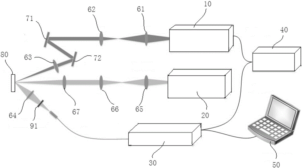
[0033] Example 1 : like figure 1 As shown, this embodiment provides a single-point fluorescence temperature measurement device, including,

[0034] A temperature probe, the temperature probe is YAG:Ce (Y 3 Al 5 o 12 :Ce) powder, which is used for mixing into the system under test or coating on the surface of the object under test 80;

[0035] The heat source laser 20 is used to emit laser pulses to the system under test or the object under test 80 to generate a transient temperature field;

[0036] A fluorescence excitation source 10, configured to emit excitation light to the measured object 80, so that the temperature probe in the transient temperature field is excited to emit anti-Stokes fluorescence and Stokes fluorescence;

[0037] The spectrum detection device 30 is used to collect the anti-Stokes fluorescence and the Stokes fluorescence emitted by the receiving temperature probe after being excited; specifically, the spectrum detection device 30 can be realized...

Embodiment 2

[0041] Example 2 : This embodiment provides a non-contact single-point fluorescence temperature measurement method with high measurement accuracy and high sampling rate, which includes the following steps:

[0042] comprising a step of calibrating the intensity ratio of anti-Stokes fluorescence and Stokes fluorescence to temperature for a specific temperature probe;

[0043] Contains the steps of incorporating the temperature probe into the system under test or painting it on the surface of the object under test 80; (the above two steps are not distinguished before and after)

[0044] Including the step of emitting laser pulses to the system under test or the object under test 80 to generate a transient temperature field;

[0045] Including emitting excitation light to the system under test or the object under test 80, so that the temperature probe in the transient temperature field is excited to emit anti-Stokes fluorescence and Stokes fluorescence;

[0046] comprising the...


PUM

PropertyMeasurementUnit
wavelengthaaaaaaaaaa

Abstract

The invention relates to the field of measurement and control, in particular to a single-point fluorescent temperature measurement device and method. YAG:Ce powder is doped into a measured system or smeared to the surface of a measured object to serve as a fluorescent temperature probe, pulse lasers serving as a heat source irradiate the measured system or the measured object to generate a transient temperature field, and meanwhile multiphonon-assisted excitation of the fluorescent temperature probe is achieved through a fluorescent excitation light source. Different from conventional excitation in an absorption band, the fluorescent temperature probe absorbs energy of one incident photon and multiple phonons at the same time to achieve excitation, and therefore fluorescence emitted by the excited fluorescent temperature probe generates anti-Stokes fluorescence. According to the scheme, the temperature dependency character of the anti-Stokes fluorescence can be enhanced, and the temperature measurement precision under high temperature can be improved.

Description

technical field [0001] The invention relates to the field of measurement and control, in particular to a single-point fluorescent temperature measuring device and a temperature measuring method. Background technique [0002] In the field of measurement and control, it is often necessary to obtain the instantaneous temperature of the measured object, such as laser (flash) heating, combustion diagnosis, engine internal temperature, temperature in the fluid field (such as gas temperature), and the instantaneous temperature of the measured object under impact loading. Temperature, most of the existing temperature measuring devices require contact measurement, and some non-contact measuring devices also have a series of problems such as low measurement accuracy, low sampling rate, and inability to correlate measurement results with time. Contents of the invention [0003] The purpose of the present invention is to overcome the problem that traditional temperature measurement de...

Claims


Application Information

Patent Timeline
Patent Type & Authority Applications(China)
IPC IPC(8): G01K11/20
CPCG01K11/20
Inventor 颜林于国洋郑闲旭宋云飞杨延强
Owner INST OF FLUID PHYSICS CHINA ACAD OF ENG PHYSICS
Why Eureka
Try Eureka