Near-eye display device and method

A near-eye display and display area technology, applied in optics, lenses, instruments, etc., can solve problems such as images that cannot be seen clearly by human eyes

Active Publication Date: 2018-03-23
BOE TECH GRP CO LTD
View PDF3 Cites 0 Cited by
  • Summary
  • Abstract
  • Description
  • Claims
  • Application Information

AI Technical Summary

Problems solved by technology

[0003] Usually, the display screen of the near-eye display is within ten centimeters from the eyeball, and such close-up images cannot be clearly seen by the human eye

Method used


Image

  • Near-eye display device and method
  • Near-eye display device and method
  • Near-eye display device and method

Examples


Embodiment 1

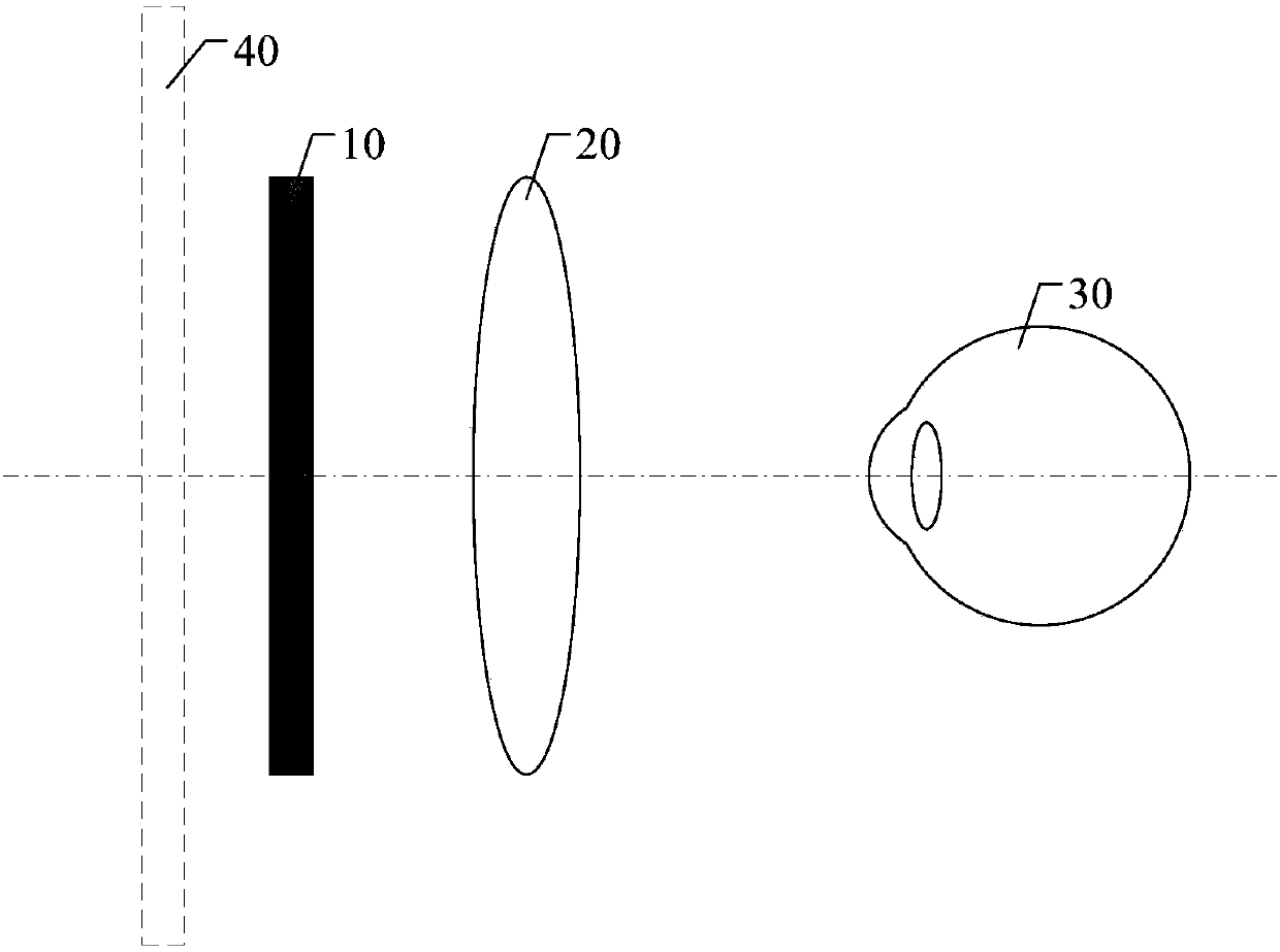
[0040] This embodiment provides a near-eye display device, such as Figure 3a As shown, the near-eye display device includes a display panel 110 and a lens module 120 , and the lens module 120 is disposed on the display side of the display panel 110 , that is, formed between the display panel 110 and the human eye 130 . The display panel 110 includes a plurality of display areas 115 arranged in an array, Figure 3a What is shown is a schematic side view of a row direction or a column direction of a plurality of display regions 115 arranged in an array. Each display area 115 includes at least one pixel unit (not shown in the figure), therefore, each display area 115 can be used for displaying pictures or pixels, and the pictures or pixels displayed by a plurality of display areas 115 can form a complete picture for Human eyes watch. The lens module 120 includes a plurality of microlenses 125 arranged in an array. The plurality of microlenses 125 include a plurality of deflect...

Embodiment 2

[0047] This embodiment provides a near-eye display device, such as Figure 3a As shown, the near-eye display device includes a display panel 110 and a lens module 120 , and the lens module 120 is disposed on the display side of the display panel 110 , that is, formed between the display panel 110 and the human eye 130 . The display panel 110 includes a plurality of display areas 115 arranged in an array. Each display area 115 includes at least one pixel unit (not shown in the figure). The lens module 120 includes a plurality of microlenses 125 arranged in an array, and each display area 115 corresponds to the microlenses 125 one by one, that is, one display area 115 corresponds to one microlens 125 . At this time, if Figure 3a As shown, except for the microlens 125 in the center of the lens module 120, other microlenses 125 in the lens module 120 can be deflection microlenses 127, so that the pictures or pixels displayed in each display area 115 pass through the virtual ima...

Embodiment 3

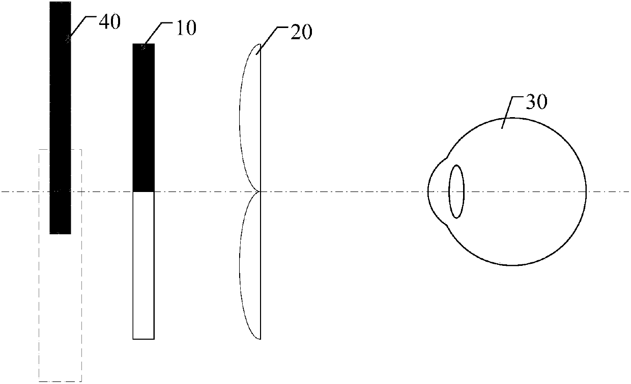
[0053] On the basis of Embodiment 1, this embodiment provides a near-eye display device, such as Figure 5 As shown, the near-eye display device includes a display panel 110 and a lens module 120 , and the lens module 120 is disposed on a side of the display panel 110 for display. The display panel 110 includes a plurality of display areas 115 arranged in an array, and each display area 115 includes at least one pixel unit (not shown in the figure), therefore, each display area 115 can be used to display a picture, and the multiple display areas 115 display The frames or pixels make up a complete picture for the human eye to see. The lens module 120 includes a plurality of microlenses 125 arranged in an array. The plurality of microlenses 125 include a plurality of deflection microlenses 127. The end of the deflection microlenses 127 close to the lens module 120 is farther away from the display panel 110 than the end farther away from the lens module 120. Near, that is, the d...


PUM


Abstract

A near-eye display device and method. The near-eye display device includes: a display panel and a lens module, the display panel includes a plurality of display areas arranged in an array, and each display area includes at least one pixel unit; the lens module includes a plurality of microlenses arranged in an array, and the plurality of microlenses include A plurality of deflection microlenses, the end of the deflection microlens close to the lens module is closer to the display panel than the end away from the lens module, each display area corresponds to at least one microlens, and adjacent parts of two adjacent display areas correspond to different Two microlenses, and the two microlenses include at least one deflection microlens, and the deflection microlens is configured so that virtual images formed by two adjacent display areas through the lens module do not overlap. Therefore, the near-eye display device can not only reduce the weight of the near-eye display device, but also solve the problem of image ghosting or color mixing in microlens imaging.

Description

technical field [0001] Embodiments of the present invention relate to a near-eye display device and a near-eye display method. Background technique [0002] At present, with the continuous development of display technology, virtual reality (Virtue Reality, VR) and near eye display (Near Eye Display, NED) technologies are attracting more and more people's attention. Near-eye display technology is a technology that can project images directly into the eyes of the viewer, thereby achieving an immersive display experience. [0003] Usually, the display screen of the near-eye display is within ten centimeters from the eyeball, and such close images cannot be seen clearly by human eyes. Therefore, the near-eye display needs to focus and project the image on the retina of the human eye through a lens, and after processing by the visual nervous system, an enlarged virtual image is presented in front of the user's eyes, which can be used in virtual reality technology or near-eye dis...

Claims


Application Information

Patent Timeline
Patent Type & Authority Patents(China)
IPC IPC(8): G02B27/01
CPCG02B27/0101G02B2027/0185G02B2027/0154G02B27/0172G02B3/0056G02F1/29G02B27/0018G02B27/01
Inventor 王灿杨亚锋高健张粲马新利王维谭纪风陈小川
Owner BOE TECH GRP CO LTD
Why Eureka
Try Eureka