Vibration data analysis system and data transmission method thereof

A data analysis and vibration data technology, applied in signal transmission systems, electrical signal transmission systems, instruments, etc., can solve the problems of harsh industrial site environment, limited number of channels, complex installation environment, etc., to avoid slow transmission speed and data transmission. Fast speed, ensuring the effect of high-speed data transmission

Active Publication Date: 2016-10-12
ANHUI RONDS SCI & TECH INC CO
View PDF6 Cites 0 Cited by
  • Summary
  • Abstract
  • Description
  • Claims
  • Application Information

AI Technical Summary

Problems solved by technology

[0002] At present, data analysis equipment on the market generally adopts a wired method to interconnect with vibration sensors. This method has three main disadvantages: (1) The industrial site environment is harsh, the installation environment is complicated, and wiring is difficult; (2) The number of channels is limited.
However, conventional wireless communication methods will also face the problems of low communication rate and poor real-time performance. Therefore, a new communication scheme between data analysis equipment and vibration sensors is needed to make up for the inherent defects of wired networking and ensure wireless networking. Offline high-speed data transmission and good real-time performance

Method used


Image

  • Vibration data analysis system and data transmission method thereof
  • Vibration data analysis system and data transmission method thereof
  • Vibration data analysis system and data transmission method thereof

Examples


Embodiment Construction

[0027] Exemplary embodiments of the present disclosure will be described in more detail below with reference to the accompanying drawings. Although exemplary embodiments of the present disclosure are shown in the drawings, it should be understood that the present disclosure may be embodied in various forms and should not be limited by the embodiments set forth herein. Rather, these embodiments are provided for more thorough understanding of the present disclosure and to fully convey the scope of the present disclosure to those skilled in the art.

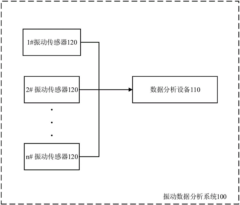
[0028] figure 1 A schematic structural diagram of a vibration data analysis system 100 according to an exemplary embodiment of the present invention is shown. Such as figure 1 As shown, the vibration data analysis system 100 includes a data analysis device 110 and at least one vibration sensor 120 associated with the data analysis device 110 . The vibration sensor 120 is arranged on the device under test, and is suitable for coll...


PUM


Abstract

The invention discloses a vibration data analysis system. The vibration data analysis system comprises data analysis equipment and at least one set of vibration sensors associated with the data analysis equipment. The data analysis equipment comprises a first communication module suitable for conducting communication according to a first communication protocol, a second communication module suitable for conducting communication according to a second communication protocol, and a communication control module suitable for broadcasting a communication establishment instruction through the first communication module, receiving vibration data through the second communication module and broadcasting a communication interruption instruction through the first communication module. Each vibration sensor comprises a first communication module suitable for conducting communication according to a first communication protocol, a second communication module suitable for conducting communication according to a second communication protocol, and a communication control module suitable for establishing connection with the data analysis equipment through the second communication module, sending vibration data to the data analysis equipment through the second communication module and interrupting connection with the data analysis equipment through the second communication module. The invention further discloses a data transmission method of the vibration data analysis system.

Description

technical field [0001] The invention relates to the field of data acquisition, in particular to a vibration data analysis system and a data transmission method thereof. Background technique [0002] At present, data analysis equipment on the market generally adopts a wired method to interconnect with vibration sensors. This method has three main disadvantages: (1) The industrial site environment is harsh, the installation environment is complicated, and wiring is difficult; (2) The number of channels is limited. The wired method needs to provide a physical interface for each vibration sensor, but due to the size limitation of the equipment, it is difficult to provide enough external interfaces; (3) Wiring distance limitation. For large equipment, the length of the cable directly limits the distribution range of the measuring points. [0003] Due to the inherent defects of wired communication, the market demand for wireless networking gradually emerged. However, conventiona...

Claims


Application Information

Patent Timeline
IPC IPC(8): G08C19/00G08C17/02
CPCG08C17/02G08C19/00
Inventor 贾维银郑旭邢动员刘刚
Owner ANHUI RONDS SCI & TECH INC CO
Why Eureka
Try Eureka