Reactor clip structure

A reactor and clip technology, applied in electrical components, transformer/inductor components, transformer/inductor magnetic cores, etc., can solve the problems of inconvenient installation and maintenance, inconvenient processing and installation, and heavy clips. To achieve the effect of convenient installation and maintenance, various installation forms, and enhanced strength

Active Publication Date: 2018-08-24
广州骏发电气设备有限公司
View PDF7 Cites 1 Cited by
  • Summary
  • Abstract
  • Description
  • Claims
  • Application Information

AI Technical Summary

Problems solved by technology

In the traditional technology, the reactor is fixed and installed in the form of foot fixing, and the installation and fixing method is single; in addition, the structural strength of the upper and lower clamps of the traditional reactor clamp structure is insufficient, which cannot meet the strength requirements of various fixed installations
Moreover, the structure of the traditional reactor clamp structure is complicated, it is inconvenient to install and maintain, and it is not conducive to the heat dissipation of the iron core.
In addition, the surface flatness of the traditional reactor clamp structure is poor, the weight of the clamp is also heavy, and it is inconvenient to process and install

Method used


Image

  • Reactor clip structure
  • Reactor clip structure
  • Reactor clip structure

Examples


Embodiment Construction

[0034] Embodiments of the present invention are described in detail below:

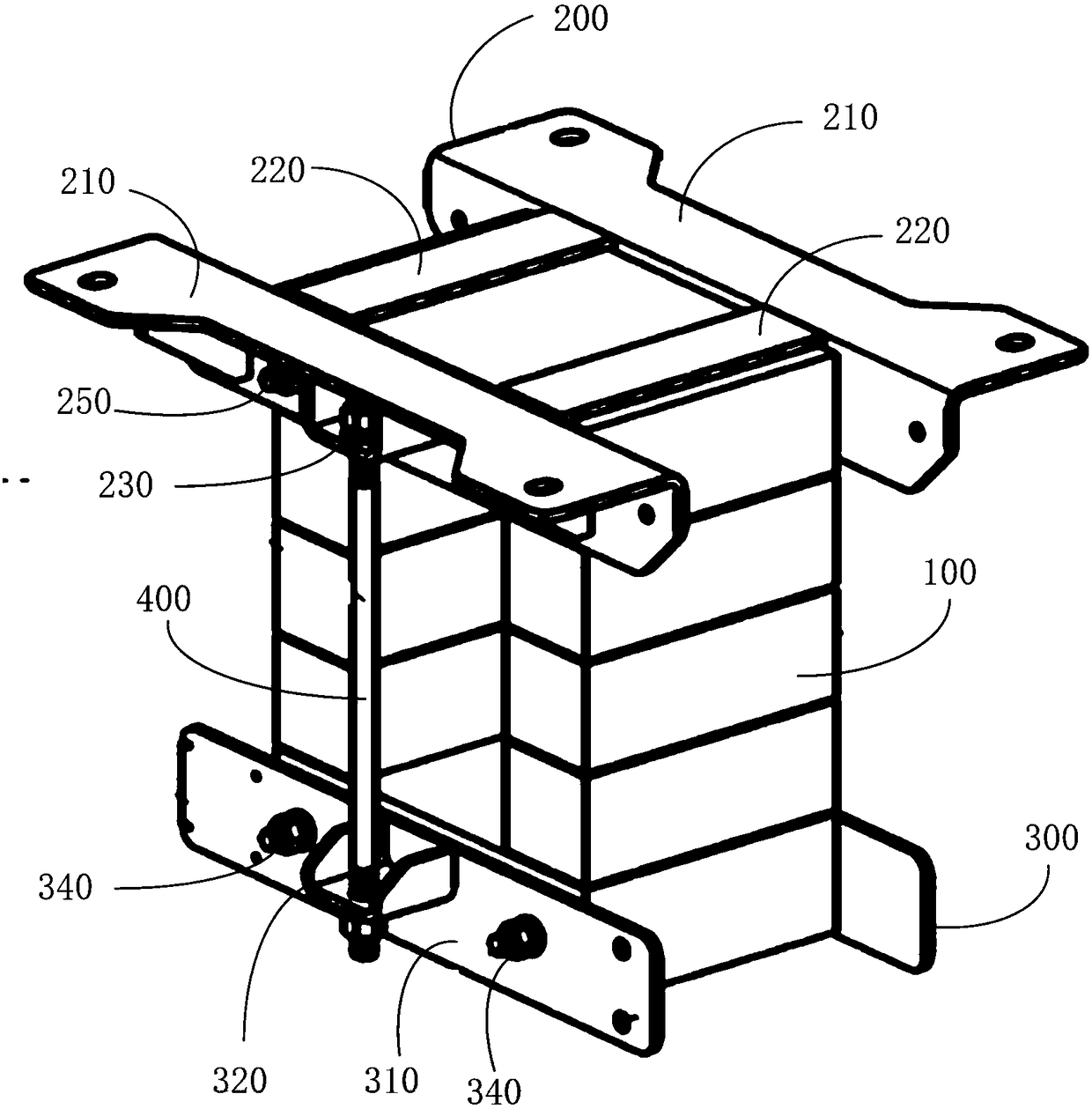
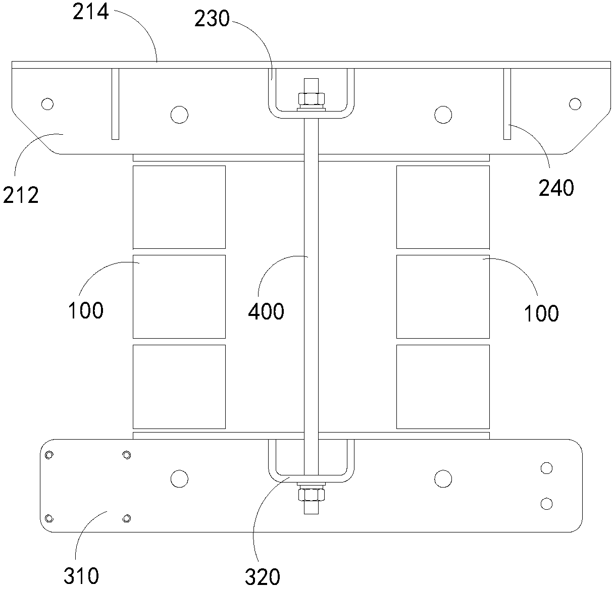
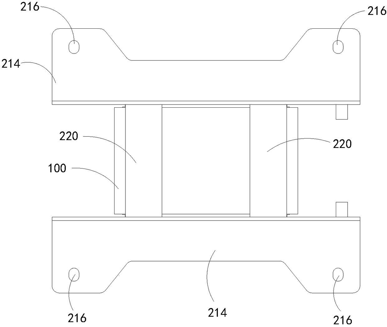
[0035] Such as figure 1 As shown, a clamp structure of a reactor includes an iron core 100, a first clamp 200 and a second clamp 300 respectively fixed at both ends of the iron core 100, and the first clamp 200 and the second clamp are fixed The clip fastener 400 of the piece 300. The first clip 200 and the second clip 300 are respectively clamped from both ends of the iron core 100, and the clip fastener 400 firmly connects the first clip 200 and the second clip 300, thereby clamping the iron core 100. prison.

[0036] And, if Figure 1 to Figure 4 As shown, the core 100 includes opposite first side surfaces and second side surfaces, and opposite first end surfaces and second end surfaces located between the first side surfaces and the second side surfaces. Such as Figure 5 As shown, the first clip 200 includes two first clips 210 respectively arranged on the first side and the second side oppo...


PUM


Abstract

The invention provides a clamping part structure of an electric reactor. The clamping part structure comprises an iron core, a first clamping part, a second clamping part and clamping part fastening parts, wherein the first clamping part and the second clamping part are fixed to the two ends of the iron core respectively, and the clamping part fastening parts are used for fixing the first clamping part and the second clamping part. The first clamping part comprises two first clamping plates and first fixing plates arranged between the two first clamping plates, and the second clamping part comprises two second clamping plates and second fixing plates arranged between the two second clamping plates; the first clamping part further comprises first fixing bases arranged on all the first clamping plates in a protruding mode, the second clamping part further comprises second fixing bases arranged on all the second clamping plates in a protruding mode and corresponding to the first fixing bases, and the two ends of each clamping part fastening part are connected to the first fixing bases and the second fixing bases respectively. The clamping part structure of the electric reactor can meet various installing requirements, is simple in structure and facilitates heat dissipating of the iron core.

Description

technical field [0001] The invention relates to the technical field of reactors, in particular to a clamp structure of a reactor. Background technique [0002] A reactor is a device used to provide inductance and is widely used in circuit systems. In the traditional technology, the reactor is fixed and installed in the form of foot fixing, and the installation and fixing method is single; in addition, the structural strength of the upper and lower clamps of the traditional reactor clamp structure is insufficient, which cannot meet the strength requirements of various fixed installations . Moreover, the structure of the conventional reactor clip is complex, inconvenient for installation and maintenance, and is not conducive to heat dissipation of the iron core. In addition, the surface flatness of the traditional reactor clamp structure is poor, the weight of the clamp is heavy, and it is inconvenient to process and install. Contents of the invention [0003] Based on th...

Claims


Application Information

Patent Timeline
Patent Type & Authority Patents(China)
IPC IPC(8): H01F27/26
CPCH01F27/266
Inventor 林桂龙刘学俊黄启浩梁龙猛
Owner 广州骏发电气设备有限公司
Why Eureka
Try Eureka