
Structured high-gain reflecting solder strip for solar cell panel

A technology of solar cells and reflective ribbons, which is applied in the direction of circuits, electrical components, semiconductor devices, etc., can solve the problems of insufficient tension of ribbons and solar cells, low reflective efficiency, and inability to bond and weld solar cells, etc., to achieve reduction Effects of current loss, distance reduction, and module power improvement

Active Publication Date: 2016-10-12
ZHEJIANG TRUMHE NEW MATERIAL CO LTD
View PDF4 Cites 12 Cited by
  • Summary
  • Abstract
  • Description
  • Claims
  • Application Information

AI Technical Summary

Problems solved by technology

[0002] In the prior art, the solder layer on the light-reflecting surface of the photovoltaic ribbon melts when it is welded to the battery sheet, and the reflection angle will change, which cannot reach the optimal reflection angle, and the reflection efficiency is not high. Moreover, the light-reflecting surface is welded on the back of the battery sheet At this time, due to the reflective structure on the light reflecting surface, it cannot be completely welded with the battery sheet, resulting in poor welding such as virtual welding, insufficient tension of the ribbon and the battery sheet, etc.

Method used


Image

  • Structured high-gain reflecting solder strip for solar cell panel
  • Structured high-gain reflecting solder strip for solar cell panel
  • Structured high-gain reflecting solder strip for solar cell panel

Examples


Embodiment Construction

[0022] The specific implementation manners of the present invention will be further described below in conjunction with the accompanying drawings, so as to make the technical solution of the present invention easier to understand and grasp.

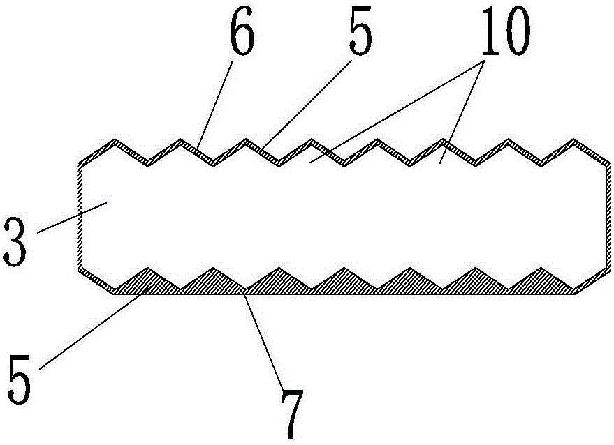
[0023] Such as Figure 1 to Figure 4 As shown, a structured high-gain reflective ribbon for solar cells includes A-section ribbon 1 and B-section ribbon 2 arranged at intervals, and the A-section ribbon 1 and the A-section ribbon 1 are arranged below The main grid line of the first battery sheet 3 is welded and connected, and the B-segment ribbon 2 is welded and connected to the back electrode of the second battery sheet 4 arranged above the B-segment ribbon 2, wherein the A-segment ribbon 1 and The section B solder strip 2 correspondingly includes a section A copper substrate 3 and a section B copper substrate 4 connected to each other, and the outer surfaces of the section A copper substrate 3 and the section B copper substrate 4 are re...


PUM


Abstract

The invention relates to a structured high-gain reflecting solder strip for a solar cell panel. The structured high-gain reflecting solder strip comprises a solder strip section A and a solder strip section B, wherein the solder strip section A and the solder strip section B comprise a copper substrate section A and a copper substrate section B. The external surfaces of the copper substrate section A and a copper substrate section B are covered and connected with solder layers which form a reflecting plane and a solder plane of the solder strip. The reflecting plane comprises a refection plane section A and a refection plane section B, and the solder plane comprises a solder plane section A and a solder plane section B. One side of the copper substrate section A and one side of the copper substrate section B are respectively provided with n triangular peaks tightly arranged. The refection plane section A and a reflecting structure formed the peaks are consistent in shape and size, and the thickness of the solder layer where the refection plane section A is situated is less than 10 micrometers. The solder layer where the refection plane section B is situated fills up the reflecting structure formed the peaks, and the top is in a horizontal plane shape. The reflected light is maximized. When the structured high-gain reflecting solder strip is welded on the back side of a cell panel, welding is reliable and current loss can be effectively reduced. The assembly power is increased.

Description

technical field [0001] The invention relates to a welding ribbon, in particular to a structured high-gain reflective welding ribbon for solar cells. Background technique [0002] In the prior art, the solder layer on the light-reflecting surface of the photovoltaic ribbon melts when it is welded to the battery sheet, and the reflection angle will change, which cannot reach the optimal reflection angle, and the reflection efficiency is not high. Moreover, the light-reflecting surface is welded on the back of the battery sheet At this time, due to the reflective structure on the light-reflecting surface, it cannot be completely welded with the battery sheet, resulting in poor welding such as virtual welding, insufficient tension of the ribbon and the battery sheet. In order to ensure the welding quality, some welding points are generally arranged on the light reflecting surface, which can be flat or arc-shaped, but these welding points will not have obvious reflection, which r...

Claims


Application Information

Patent Timeline
Patent Type & Authority Applications(China)
IPC IPC(8): H01L31/05H01L31/054
Inventor 邓琴
Owner ZHEJIANG TRUMHE NEW MATERIAL CO LTD
Learn More