
High voltage electric power piercing connector

A technology of piercing wire clips and high-voltage power, which is applied in the direction of circuits, electrical components, conductive connections, etc., can solve problems such as easy loosening and poor firmness, and achieve excellent anti-loosening, improve service life, and ensure stability and reliability.

Active Publication Date: 2016-10-12
YANCHENG POWER SUPPLY CO STATE GRID JIANGSU ELECTRIC POWER CO +4
View PDF5 Cites 7 Cited by
  • Summary
  • Abstract
  • Description
  • Claims
  • Application Information

AI Technical Summary

Problems solved by technology

However, the traditional puncture clamp also has shortcomings. The pressure of the clamp depends on the pressure of the ordinary bolt assembly, which is poor in firmness and easy to loosen.

Method used


Image

  • High voltage electric power piercing connector

Examples


Embodiment Construction

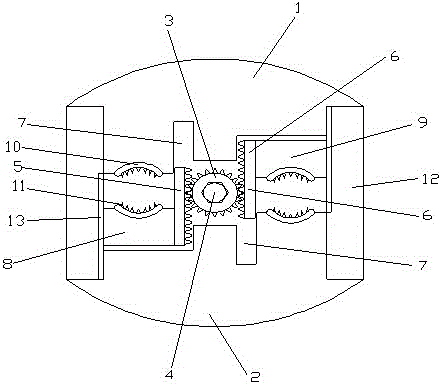
[0011] Such as figure 1 A high-voltage electric puncture wire clip shown includes a wire pressing upper cover 1 and a wire pressing lower cover 2, and a gear 3 is provided at the middle position between the wire pressing upper cover 1 and the wire pressing lower cover 2, and the gear 3. A fixed bolt 4 is arranged horizontally on the upper side. The left side of the gear 3 meshes with the lower rack 5, and the right side meshes with the upper rack 6. The line pressure upper cover 1 corresponding to the lower rack 5 is provided with The rack limit groove 7, and the line pressing cover 2 corresponding to the upper rack 6 is also provided with a rack limit groove 7, and the left side of the bottom of the lower rack 5 is fixedly provided with an engaging lower cover 8, The right side of the top of the upper rack 6 is provided with an engaging upper cover 9, and the engaging upper cover 9 and the engaging lower cover 8 are provided with an arc-shaped insulating sheath 10, and the in...


PUM


Abstract

The invention discloses a high voltage electric power piercing connector. The high voltage electric power piercing connector comprises an upper line voltage cover and a lower line voltage cover, wherein a gear is arranged at a middle portion between the upper line voltage cover and the lower line voltage cover, the gear is transversely provided with a fixing bolt, a left side of the gear is engaged with a lower tooth bar, a right side of the gear is engaged with an upper tooth bar, the upper line voltage cover corresponding to the lower tooth bar is provided with a tooth bar limit groove, the lower line voltage cover corresponding to the upper tooth bar is further provided with a tooth bar limit groove, a left side of a lower portion of the lower tooth bar is fixedly provided with a lower engagement cover, a right side of an upper portion of the upper tooth bar is provided with an upper engagement cover, the upper engagement cover and the lower engagement cover are respectively provided with an arc-shaped insulation sheath, and the insulation sheaths are provided with piercing blades. Compared with a mode of utilizing a traditional bolt assembly to clamp an electric power cable, the high voltage electric power piercing connector realizes clamping of the electric power cable through mutual engagement of the gear and the tooth bars, the excellent anti-loosing effect is realized, and long-term stable reliable operation is effectively guaranteed.

Description

technical field [0001] The invention relates to the technical field of power fittings for overhead lines, in particular to a high-voltage power puncture clamp. Background technique [0002] In the construction of overhead power lines, when the cable needs to be branched or spliced, it is necessary to connect two insulated wires together with a splicing clamp. The connection clamp, especially the piercing type connection clamp, has the characteristics of easy installation, low cost, safety, reliability and maintenance-free. Cable branches can be made without cutting off the main cable or stripping the insulation layer of the cable. The joints are completely insulated and can be used for live work, and can be branched at any position on the cable; no terminal box or junction box is needed; and the joints are resistant to twisting, Shockproof, waterproof, anti-corrosion and aging; the comprehensive benefits are obvious, and the cost performance is better than the traditional c...

Claims


Application Information

Patent Timeline
IPC IPC(8): H01R4/28H01R4/24H01R4/26H01R11/01
CPCH01R4/24H01R4/26H01R4/28H01R11/01
Inventor 王春雨谢以松宋晓涛叶鹏
Owner YANCHENG POWER SUPPLY CO STATE GRID JIANGSU ELECTRIC POWER CO
Learn More