Wiring structure of a transverter and its control method

A technology of wiring structure and control method, applied to AC network circuits, electrical components, reactive power compensation, etc., can solve problems such as grid isolation and accident expansion, improve reliability and safety, and implement simple and flexible methods Effect

Active Publication Date: 2016-10-12
NR ELECTRIC CO LTD +1
View PDF3 Cites 0 Cited by
  • Summary
  • Abstract
  • Description
  • Claims
  • Application Information

AI Technical Summary

Problems solved by technology

When it is necessary to exit, the device is bypassed through the bypass switch on the series side, which cannot be completely isolated from the grid; even if there is a problem with the bypass switch or the series side, the transmission line can only be shut down, resulting in the expansion of the accident

Method used


Image

  • Wiring structure of a transverter and its control method
  • Wiring structure of a transverter and its control method
  • Wiring structure of a transverter and its control method

Examples


Embodiment Construction

[0020] The technical solutions of the present invention will be described in detail below in conjunction with the accompanying drawings.

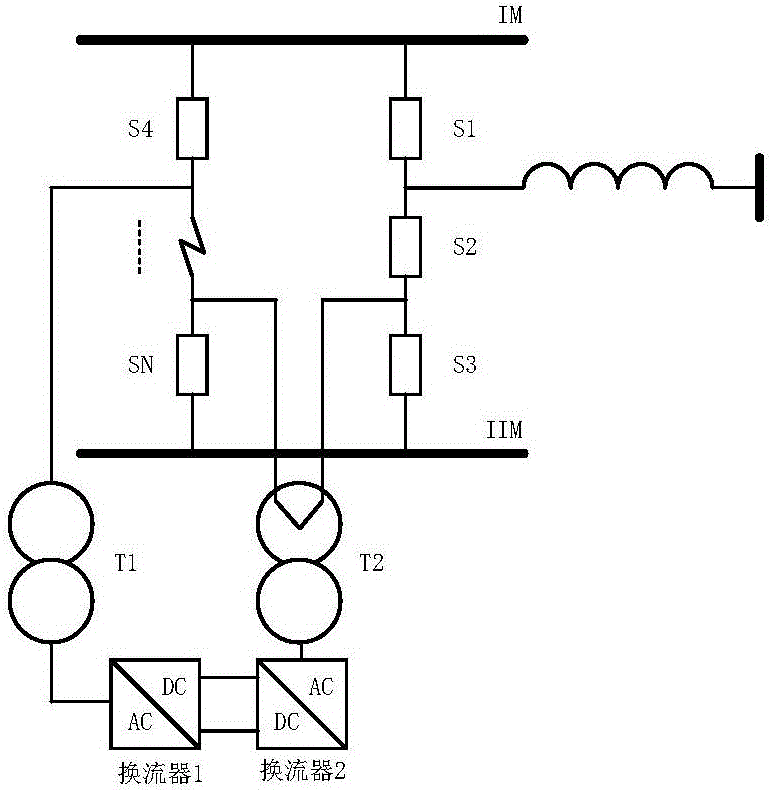
[0021] Such as figure 1 As shown, the present invention provides a wiring structure of a converter, which is suitable for a unified power flow controller, a convertible static compensator, a static synchronous series compensator, and a unified power quality regulator. The most basic wiring structure includes a converter converter, double busbar (IM, IIM), 3 / 2 circuit breaker wiring branch, multiple circuit breaker wiring branch (including at least 2 circuit breakers), 1 series transformer and 1 transmission line, of which, 3 / 2 The circuit breaker wiring branch includes 3 circuit breakers S1, S2, S3 connected in sequence, and the two ends of the 3 / 2 circuit breaker wiring branch are respectively connected to the double busbar IM, IIM; the multi-circuit breaker wiring branch includes sequentially connected circuit breakers S4, ..., SN, the t...


PUM


Abstract

The invention discloses a wiring structure of a transverter and its control method. The structure comprises a first transverter, a double busbar, a 3 / 2 circuit breaker wiring branch, a multi-breaker wiring branch, a series transformer and a transmission line wherein the 3 / 2 circuit breaker wiring branch and the multi-breaker wiring branch are connected to the double busbar respectively. The side winding of the series transformer is connected with the first transverter through star or angle type connection. The line-side winding of the series transformer is connected to any node of the 3 / 2 breaker wiring branch and the multi-breaker wiring branch; a transmission line is connected to other nodes in the 3 / 2 breaker wiring branch except those of the line side winding. Such structure has high reliability and can be simply implemented with flexibility. The invention also discloses a control method for such a wiring structure of a transverter.

Description

technical field [0001] The invention belongs to the field of flexible AC power transmission, and in particular relates to a wiring structure of a converter and a control method thereof. Background technique [0002] The equipment of flexible AC transmission system (FACTS) can be divided into series compensation device, parallel compensation device and comprehensive control device. Among them, the parallel compensation device can be directly connected to various levels of power grids, and the series compensation device and comprehensive control device are due to one end It needs to be connected to the power grid in series, and its connection method needs to be studied comprehensively in terms of reliability, flexibility and security. [0003] Among series compensation devices and integrated control devices, Static Synchronous Series Compensator (SSSC), Unified Power Flow Controller (UPFC), Interline Power Flow Controller (IPFC) and Switchable Static Compensator (CSC) can all ...

Claims


Application Information

Patent Timeline
Patent Type & Authority Applications(China)
IPC IPC(8): H02J3/18
CPCH02J3/1814Y02E40/30
Inventor 黄如海卢宇董云龙潘磊邱德峰姜崇学鲁江汪楠楠李钢丁久东王柯胡兆庆王辉胡仙来随顺科
Owner NR ELECTRIC CO LTD
Why Eureka
Try Eureka