Permanent magnet synchronous motor and its rotor

A permanent magnet synchronous and motor technology, applied in synchronous machines, synchronous machine parts, electric components and other directions, can solve the problems of unpracticality and complex structure, and achieve simple structure, stable operation, and good weak field speed expansion capability. Effect

Inactive Publication Date: 2018-11-09
SHANGHAI DIANJI UNIV
View PDF5 Cites 0 Cited by
  • Summary
  • Abstract
  • Description
  • Claims
  • Application Information

AI Technical Summary

Problems solved by technology

However, these permanent magnet synchronous motor structures have some shortcomings, such as complex structure, not practical and other problems

Method used


Image

  • Permanent magnet synchronous motor and its rotor
  • Permanent magnet synchronous motor and its rotor
  • Permanent magnet synchronous motor and its rotor

Examples


Embodiment Construction

[0025] In order to make the above objects, features and advantages of the present invention more comprehensible, specific implementations of the present invention will be described in detail below in conjunction with the accompanying drawings.

[0026] Embodiments of the present invention will now be described in detail with reference to the accompanying drawings. Reference will now be made in detail to the preferred embodiments of the invention, examples of which are illustrated in the accompanying drawings. Wherever possible, the same numbers will be used throughout the drawings to refer to the same or like parts. In addition, although the terms used in the present invention are selected from well-known and commonly used terms, some terms mentioned in the description of the present invention may be selected by the applicant according to his or her judgment, and the detailed meanings thereof are set forth herein described in the relevant section of the description. Furtherm...


PUM


Abstract

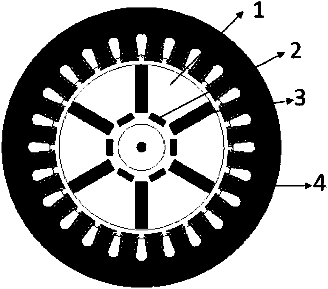
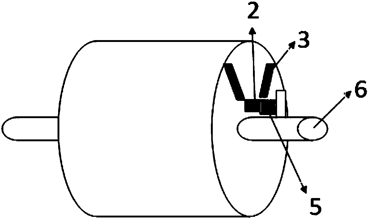
The invention relates to a permanent-magnet synchronous motor and a rotor thereof. The permanent-magnet synchronous motor comprises a stator and the rotor. The rotor comprises a rotor core, a magnetic path assembly installed in the rotor core, and a motor shaft penetrating through the rotor. The magnetic path assembly comprises multiple tangential permanent magnets and multiple radial permanent magnets. The tangential permanent magnets are evenly distributed in the radial direction of the rotor core, each radial permanent magnet is arranged between two adjacent tangential permanent magnets, the two opposite adjacent sides of two adjacent tangential permanent magnets and the side, facing the stator, of the corresponding radial permanent magnet between the two adjacent tangential permanent magnets have the same polarity, and the radial permanent magnets can move. The permanent-magnet synchronous motor has good flux weakening speed increase capacity, can stably run at high rotating speed, and is simple in structure.

Description

technical field [0001] The invention relates to a permanent magnet synchronous motor, in particular to a permanent magnet synchronous motor with a rotor and a stator. Background technique [0002] The current existing permanent magnet synchronous motors are difficult to adjust due to the permanent magnet excitation. In the case of limited power capacity, there is a problem of difficulty in field weakening and speed expansion when operating above the base speed, which limits the speed regulation range of permanent magnet synchronous motors. [0003] In order to improve the field-weakening speed regulation range of permanent magnet synchronous motors, scholars at home and abroad have proposed various structures of permanent magnet synchronous permanent magnet synchronous motors, such as hybrid excitation structure, external magnetic yoke rotor structure, layered or segmented permanent magnet structure, Composite rotor structure, axial lamination rotor structure, variable reluc...

Claims


Application Information

Patent Timeline
Patent Type & Authority Patents(China)
IPC IPC(8): H02K1/27H02K7/00H02K21/02
CPCH02K1/2746H02K7/00H02K21/021
Inventor 田玉冬姜春辉
Owner SHANGHAI DIANJI UNIV
Why Eureka
Try Eureka