
Vibration energy collector

A vibration energy harvesting, folding and pressing technology, applied in the directions of generators/motors, piezoelectric effect/electrostrictive or magnetostrictive motors, electrical components, etc. To achieve the effect of high collection efficiency

Active Publication Date: 2016-10-12
ZHENGZHOU UNIV
View PDF5 Cites 24 Cited by
  • Summary
  • Abstract
  • Description
  • Claims
  • Application Information

AI Technical Summary

Problems solved by technology

The energy harvester that is usually studied is to respond to the vibration excitation in a certain direction to collect energy, and it needs a relatively high operating frequency. In the lower frequency range, such as the frequency of human motion is only below 10Hz, it cannot be effective. Harvesting vibration energy

Method used


Image

  • Vibration energy collector
  • Vibration energy collector
  • Vibration energy collector

Examples


Embodiment 1

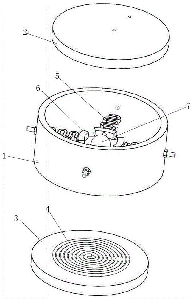
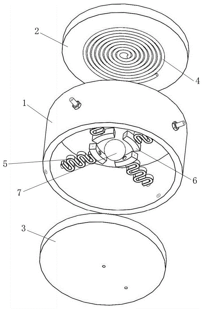
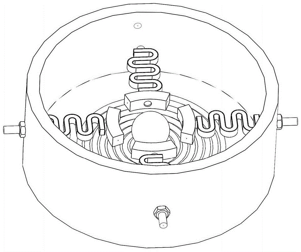
[0024] A vibration energy harvester, comprising a bracket, a cover plate is arranged above the bracket, a bottom plate is arranged under the bracket, and at least three folded piezoelectric beams are arranged inside the bracket. A piezoelectric sheet is arranged inside the folded piezoelectric beam, electrodes with different polarities are arranged on both sides of the folded piezoelectric beam, and the electrodes are connected with a power management circuit. There is a distance between the bent parts of the folded piezoelectric beam, and the distance can make the folded piezoelectric beam produce piezoelectric effect. The two ends of the folded piezoelectric beam are a fixed end and a cantilever end, the fixed end of the folded piezoelectric beam is fixed on the support, and the cantilever end of the folded piezoelectric beam extends to the middle of the support. A sphere is arranged in the space surrounded by the cantilever ends of the folded piezoelectric beams, and a dist...

Embodiment 2

[0029] A vibration energy harvester comprises a bracket 1, a cover plate 2 is arranged above the bracket 1, and a bottom plate 3 is arranged under the bracket 1. The support 1 is provided with at least three evenly distributed folded piezoelectric beams 5, and a space is provided between the bending parts of the folded piezoelectric beams 5, and the two ends of the folded piezoelectric beams 5 are fixed ends and cantilever ends, and the folding The fixed end of the piezoelectric beam 5 is fixed on the support, the cantilever end of the folded piezoelectric beam 5 extends to the middle of the support, and a sphere is arranged in the space surrounded by the cantilever end of the folded piezoelectric beam 5, and the cantilever of the folded piezoelectric beam 5 A distance is provided between the ends, and a distance is provided between the sphere 7 and the cantilever end of the folded piezoelectric beam 5 .

[0030] The folded piezoelectric beams 5 are evenly distributed, on the ...

Embodiment 3

[0042] Such as figure 1 , figure 2 , image 3 and Figure 4 As shown, a vibration energy harvester includes a bracket 1, a cover plate 2 is arranged above the bracket 1, a bottom plate 3 is arranged below the bracket 1, and a helical coil 4 is arranged on the inner surfaces of the cover plate 2 and the bottom plate 3. The bracket 1 is a cylindrical bracket, which is convenient for disposing the folded piezoelectric beam 5 on the bracket 1 . Four evenly distributed folded piezoelectric beams 5 are arranged inside the bracket 1 . The number of folded piezoelectric beams 5 is set to 4, and the folded piezoelectric beams 5 are evenly distributed along the circumference of the support 1. The four folded piezoelectric beams 5 are on the same plane, and the plane is parallel to the helical coil 4, so that each folded piezoelectric beam 5 The shaped piezoelectric beam 5 can be received in the middle of the support 1 as evenly as possible during work. The two ends of the folded p...


PUM


Abstract

The invention discloses a vibration energy collector. The vibration energy collector comprises a bracket, wherein a cover plate is arranged above the bracket; a bottom plate is arranged below the bracket; at least three uniformly distributed foldable piezoelectric beams are arranged in the bracket; spacings are formed between the bent parts of the foldable piezoelectric beams; a fixed end and a cantilever end are arranged at the two ends of each foldable piezoelectric beam; the fixed end of each foldable piezoelectric beam is fixed on the bracket; the cantilever end of each foldable piezoelectric beam extends to the middle part of the bracket; a sphere body is arranged in the space which is surrounded by the cantilever ends of the foldable piezoelectric beams; spacings are formed between the cantilever ends of the foldable piezoelectric beams; and spacings are formed between the sphere body and the cantilever ends of the foldable piezoelectric beams. According to the vibration energy collector, the piezoelectric foldable beams are distributed around the sphere body with mass; when the sphere body moves under the external vibration and excitation effect to apply acting force on the surrounding piezoelectric foldable beams to enable the piezoelectric foldable beams to be deformed to generate stress, piezoelectric charges are generated on the two sides of the foldable piezoelectric beams due to a piezoelectric effect; then the piezoelectric charges pass through the electrodes on the two sides of the piezoelectric foldable beams to be collected by a power supply management circuit, so that the collection of the vibration energy is realized; and in addition, the collecting efficiency is high.

Description

technical field [0001] The invention relates to the technical field of energy harvesters, in particular to a vibration energy harvester, which can respond to vibration excitations in various directions, realize energy collection, convert vibration energy in the environment into electrical energy, and improve the efficiency of energy collection . Background technique [0002] With the gradual consumption of petrochemical energy, energy issues have gradually attracted worldwide attention. While nature endows us with various forms of energy, most of the energy is currently not being utilized. For example, solar energy is converted into electrical energy through photoelectric conversion, waste heat is converted into electrical energy through thermoelectric effect, energy harvested through biochemical reactions, and vibration energy in the environment is converted into electrical energy through component movement. Vibration energy harvesting can be applied to various fields. Ma...

Claims


Application Information

Patent Timeline
IPC IPC(8): H02N2/18H02K35/02
CPCH02K35/02H02N2/183
Inventor 苏宇锋张坤段智勇郭丹叶志通秦立振张振宇
Owner ZHENGZHOU UNIV
Features
  • Generate Ideas
  • Intellectual Property
  • Life Sciences
  • Materials
  • Tech Scout
  • Unparalleled Data Quality
  • Higher Quality Content
  • 60% Fewer Hallucinations
Learn More