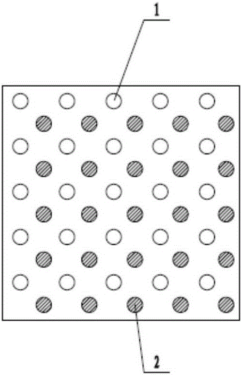
Technology of large-energy dynamic-compaction-treated foundation
A large-energy, ground-based technology, applied in infrastructure engineering, soil protection, construction, etc., can solve problems such as methods and depths that cannot meet the requirements, and achieve the effect of increasing depth, significant effect, and reducing the number of passes
- Summary
- Abstract
- Description
- Claims
- Application Information
AI Technical Summary
Problems solved by technology
Method used
Image
Examples
Embodiment 1
[0042] (1) Construction survey and site leveling for the first time
[0043] ①Calibration of instruments: Calibrate the measuring instruments GPS, level and steel ruler measuring instruments;
[0044] ② Level the construction area for the first time, and dig drainage ditches on both sides of the dynamic compaction area;
[0045] ③Positioning and setting out: Use measuring instruments to measure and release the four corner pile positions in the dynamic compaction area;
[0046] (2) The first time point ramming
[0047] ①Mark the position of the first strong compaction point and measure the original ground elevation;
[0048] ② Align the rammer of the crane with the ramming point, and measure the height of the hammer top before ramming;
[0049] ③ Lift the rammer to the predetermined height, turn on the dragging device, put down the hook after the rammer falls freely, measure the elevation of the rammer top, and stop when the average tamping weight of the last two hits is 30m...
Embodiment 2
[0073] (1) Construction survey and site leveling for the first time
[0074] ①Calibration of instruments: Calibrate the measuring instruments GPS, level and steel ruler measuring instruments;
[0075] ② Level the construction area for the first time, and dig drainage ditches on both sides of the dynamic compaction area;
[0076] ③Positioning and setting out: Use measuring instruments to measure and release the four corner pile positions in the dynamic compaction area;
[0077] (2) The first time point ramming
[0078] ①Mark the position of the first strong compaction point and measure the original ground elevation;
[0079] ② Align the rammer of the crane with the ramming point, and measure the height of the hammer top before ramming;
[0080]③ Lift the rammer to the predetermined height, turn on the dragging device, put down the hook after the rammer falls freely, measure the elevation of the rammer top, and stop when the average tamping weight of the last two hits is 30m;...
Embodiment 3
[0104] (1) Construction survey and site leveling for the first time
[0105] ①Calibration of instruments: Calibrate the measuring instruments GPS, level and steel ruler measuring instruments;
[0106] ② Level the construction area for the first time, and dig drainage ditches on both sides of the dynamic compaction area;
[0107] ③Positioning and setting out: Use measuring instruments to measure and release the four corner pile positions in the dynamic compaction area;
[0108] (2) The first time point ramming
[0109] ①Mark the position of the first strong compaction point and measure the original ground elevation;
[0110] ② Align the rammer of the crane with the ramming point, and measure the height of the hammer top before ramming;
[0111] ③ Lift the rammer to the predetermined height, turn on the dragging device, put down the hook after the rammer falls freely, measure the elevation of the rammer top, and stop when the average tamping weight of the last two hits is 28m...
PUM
 Abstract
Description
Claims
Application Information
 - R&D
- Intellectual Property
- Life Sciences
- Materials
- Tech Scout
- Unparalleled Data Quality
- Higher Quality Content
- 60% Fewer Hallucinations
Browse by: Latest US Patents, China's latest patents, Technical Efficacy Thesaurus, Application Domain, Technology Topic, Popular Technical Reports.
© 2025 PatSnap. All rights reserved.Legal|Privacy policy|Modern Slavery Act Transparency Statement|Sitemap|About US| Contact US: help@patsnap.com


