Fishing rod holder and fishing rod apparatus

A rod rack and rack body technology, applied in the field of fishing equipment, can solve the problems of easy shaking of fishing rods, inconvenient use, difficulty in adapting to different occasions, etc., and achieve the effects of lightening the burden, convenient use, and simple structure

Pending Publication Date: 2016-10-26
陈亚荣
10 Cites 0 Cited by

AI-Extracted Technical Summary

Problems solved by technology

[0002] During the fishing process, if the fishing rod is held in the hand, the fishing rod is easy to shake, it is difficult to accurately observe the subtle changes of the rod tip, etc., and it is impossible to accurately judge whether there is a fish hooked, and holding the fishing rod for a long time will make the ...

Method used

...

Abstract

The invention provides a fishing rod holder and a fishing rod apparatus and belongs to the field of fishing tools. The fishing rod support includes a holder body, a moving piece, a positioning piece and a rod rack for placing a fishing rod. The holder body includes a main body, a handle and a first clamping piece. The handle and the first clamping piece are fixed to the main body. The moving piece includes a sliding rod and a second clamping body. The sliding rod is in sliding arranged to the holder body and is fixed through the positioning piece. The second clamping piece is in fixed connection to the sliding rod. The first clamping piece and the second clamping piece for a clamping zone therebetween with adjustable distance. The rod rack is arranged on the main body. When the fishing rod holder is in usage, the width of the clamping zone is adjusted, and the first clamping piece and the second clamping piece clamp a to-be-clamped structure, and then the fishing rod is placed inside a receiving groove and is fixed through the positioning piece. The fishing rod holder has simple structure, is easy to use, and is applicable to different scenarios.

Application Domain

Other angling devices

Technology Topic

FishingBiochemical engineering

Image

  • Fishing rod holder and fishing rod apparatus
  • Fishing rod holder and fishing rod apparatus
  • Fishing rod holder and fishing rod apparatus

Examples

  • Experimental program(2)

Example Embodiment

[0045] Example 1:
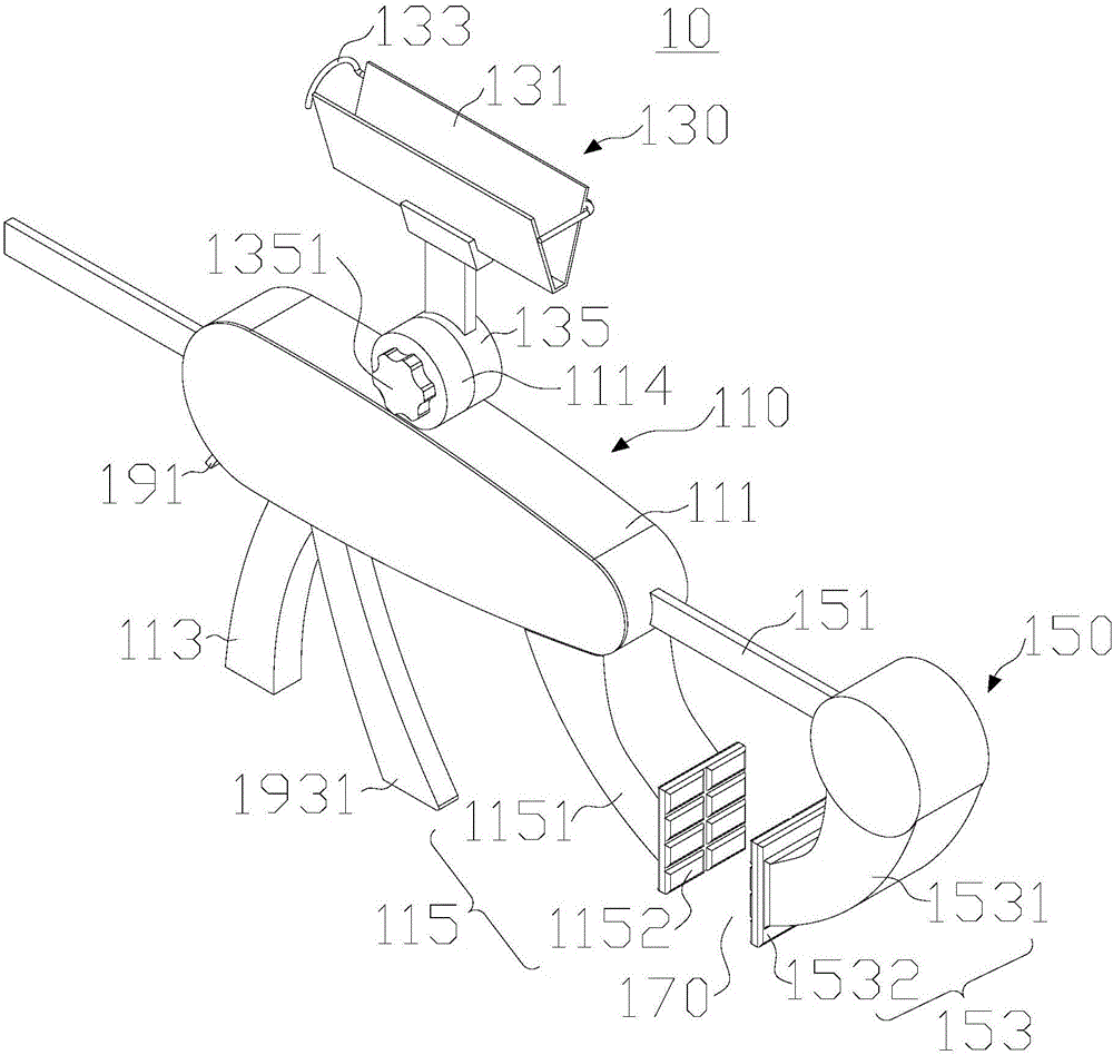
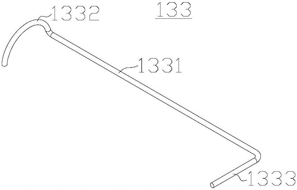
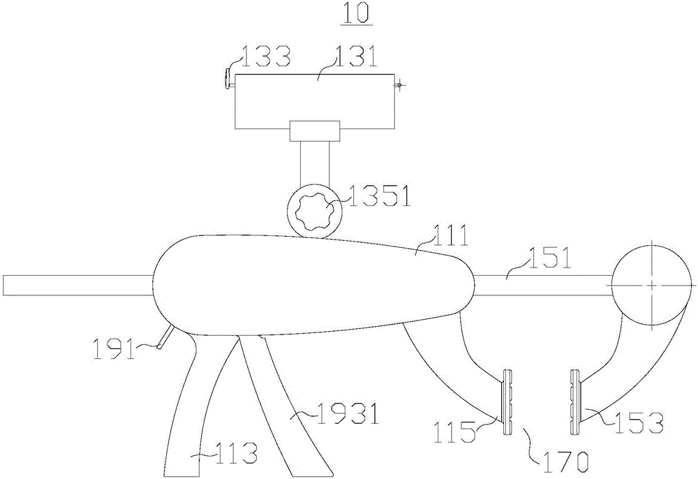
[0046] Please refer to figure 1 , image 3 , Embodiment 1 of the present invention provides a bridge fishing bracket 10, which is mainly composed of a frame body 110, a rod frame 130, a movable part 150, and a positioning part 190. Each part of the bridge fishing bracket 10 will be described in detail below:
[0047] The frame 110 includes a main body 111, a handle 113 and a first clamping member 115. The handle 113 and the first clamping member 115 are both fixedly arranged on the main body 111. The handle 113 is used for grasping. The connection manner between the clamping member 115 and the main body 111 is not limited, for example, integral molding, welding, detachable connection, etc. may be adopted.
[0048] In this embodiment, the first clamping member 115 includes a first connecting section 1151 and a first clamping portion 1152. The first clamping section may be an arc-shaped member. One end of the first clamping section is fixed to the main body 111. The other end of a clamping section is fixedly connected to the first clamping portion 1152, and the side of the first clamping portion 1152 away from the first connection section 1151 may be provided with an anti-slip structure, such as anti-slip lines, anti-slip mats, etc.
[0049] The rod holder 130 is used for erecting fishing rods, and various connection methods such as fixed connection, movable connection, and detachable connection can be adopted between the rod holder 130 and the body 111.
[0050] Please refer to figure 1 The rod holder 130 is provided with a receiving groove 131 and a fixing member 133. The fishing rod can be placed in the receiving groove 131. The direction of the receiving groove 131 can be set as required. The fishing rod is placed in the receiving groove 131 and fixed by the fixing member 133. , To prevent the fishing rod from slipping off. The receiving groove 131 may be a C-shaped groove, a V-shaped groove, a trapezoidal groove, or the like.
[0051] The rod frame 130 and the main body 111 can be fixedly connected. In this embodiment, the rod frame 130 is rotatably arranged on the main body 111 and fixed by fasteners. The axis of rotation of the rod frame 130 is in the direction of the sliding rod 151. Vertically, specifically, the main body 111 is provided with a first connecting portion 1114, the pole frame 130 is provided with a second connecting portion 135, both the first connecting portion 1114 and the second connecting portion 135 are provided with through holes, and the first connecting portion 1114 It is fixed with the second connecting portion 135 by threaded fasteners. One end of the threaded fastener is a knob 1351, and the other end is sleeved with a nut. In addition, the first connecting portion 1114 or the second connecting portion 135 is provided for accommodating the nut The shape and size of the groove match the nut. When you turn the knob 1351, you only need to make sure that the nut cannot be separated from the groove to easily operate.
[0052] Of course, the rotation direction of the rod holder 130 can also be set as required. The rod holder 130 can be rotated so that the direction of the receiving groove 131 can be adjusted, thereby adjusting the direction of the fishing rod, such as adjusting the tilt angle of the fishing rod, etc. More convenient.
[0053] The fixing member 133 is mainly used to fix the fishing rod in the receiving groove 131 to prevent the fishing rod from detaching from the receiving groove 131. The form of the fixing member 133 is not limited. For example, the fixing member 133 is a clip or a buckle. In this embodiment, a structure of the fixing member 133 is provided: please refer to figure 2 The fixing member 133 includes a connecting rod 1331, a pressing rod 1332 and an arc-shaped rod 1333. The connecting rod 1331 is arranged along the direction of the receiving groove 131, and the connecting rod 1331 is rotatably arranged on the rod holder 130. When the fishing rod is placed in the receiving groove 131, the fish The rod presses down the pressing rod 1332 and the arc-shaped rod 1333 hooks the fishing rod.
[0054] The movable part 150 can move relative to the main body 111. The movable part 150 includes a sliding rod 151 and a second clamping part 153. The sliding rod 151 is rod-shaped. Of course, the sliding rod 151 may be in the form of a round rod, a square rod, a bar, etc. , The sliding rod 151 is slidably disposed on the frame 110 and fixed by the positioning member 190, the second clamping member 153 can be fixed to one end of the sliding rod 151, and the end of the sliding rod 151 away from the second clamping member 153 is provided with a limit block, The limiting block is used to limit the sliding range of the sliding rod 151. When the sliding rod 151 slides to a certain position, the limiting block resists the body 111 to prevent the sliding rod 151 from sliding further. The first clamping member 115 is located between the second clamping member 153 and the handle 113. In this embodiment, the receiving groove 131 is arranged along the direction of the sliding rod 151.
[0055] In this embodiment, the structure of the second clamping member 153 may be the same as the structure of the first clamping member 115, that is, the second clamping member 153 includes a second connecting section 1531 and a second clamping portion 1532. The holding section may be an arc-shaped piece, one end of the second holding section is fixed to one end of the sliding rod, the other end of the second holding section is fixedly connected with the second holding part 1532, and the second holding part 1532 is far away from the second holding part 1532. One side of the connecting section 1531 may be provided with an anti-skid structure, such as an anti-skid pattern, an anti-skid pad, etc. The first clamping portion 1152 and the second clamping portion 1532 are disposed opposite to each other, and a clamping area 170 with an adjustable distance is formed between the first clamping member 115 and the second clamping member 153.
[0056] The first clamping member 115 is fixed relative to the main body 111, and the second clamping member 153 can approach or be far away from the first clamping member 115 under the drive of the sliding rod 151, that is, the first clamping member 115 and the second clamping member 115. The spacing between the clamping members 153 can be adjusted as required. The first clamping member 115 and the second clamping member 153 cooperate with each other, so that the clamping area 170 clamps structures of different sizes (such as bridge piers, etc., for ease of description) , The following defines this part as a fixed seat).
[0057] After the first clamping member 115 and the second clamping member 153 clamp the fixing seat, the sliding rod 151 is locked by the positioning member 190, so that the bridge fishing bracket 10 is firmly fixed on the fixing seat. The positioning member 190 has various structures. For example, the positioning member 190 is a bolt, a positioning through hole is provided on the body 111, and an internal thread is provided in the positioning through hole. The bolt is threadedly engaged with the through hole, and the bolt penetrates and extends through the through hole. The sliding rod 151 is pressed into the main body 111. When necessary, the bolt is first screwed to separate the bolt from the sliding rod 151. The sliding rod 151 can slide in the main body 111 to adjust the position of the second clamping member 153.
[0058] In this embodiment, an optional structure of the positioning member 190 is provided, please refer to Figure 4 The positioning member 190 includes a fixing member 191, a return spring and an adjusting member 193.
[0059] Please refer to Figure 5 , The fixed clip 191 is rotatably arranged on the body 111, and the fixed clip 191 is rotatably arranged on the body 111 through a rotating shaft. The return spring can be a compression spring, a spring, a torsion spring, etc. The fixed clip 191 includes a locking portion 1911 and a control portion 1912, The locking portion 1911 is provided with a first through hole, the sliding rod 151 is penetrated through the first through hole, the size of the first through hole may be larger than the size of the sliding rod 151, and the return spring pierces the first through hole The edge of the hole is pressed and fixed to the slide bar 151, that is, the return spring makes the fixed clip 191 rotate a certain angle around the rotation axis, and the center line of the first through hole (the first through hole can be simplified as a standard through hole, for example The square hole, etc.) is inclined with respect to the direction of the sliding rod 151, and the position of the edge of the first through hole changes until it is pressed against the sliding rod 151.
[0060] The end of the first through hole close to the rotating shaft is the first end, the end of the first through hole away from the rotating shaft is the second end, and the end of the sliding rod 151 where the second clamping member 153 is provided is a clamp For the holding end, the distance between the first end and the clamping end is greater than the distance between the second end and the clamping end.
[0061] The advantage of this design is that image 3 In the normal situation, the second end is press-fitted with the slide bar 151. To move the slide bar 151 to the left, a certain degree of force is used (the force is determined by the return spring, of course, if the return spring If the pressure applied to the fixing clip 191 is large enough, it is difficult for the sliding rod 151 to slide under the action of external force) so that the fixing clip 191 has a tendency to rotate counterclockwise, thereby reducing the distance between the fixed second end and the sliding rod 151. The slide bar 151 can slide to the left due to the pressure and friction of the slide bar 151; and if the slide bar 151 is to move to the right, due to the friction between the second end and the slide bar 151, the fixed clip 191 has a tendency to rotate clockwise , The fixing clip 191 further presses the sliding rod 151, the sliding of the sliding rod 151 is very laborious, which can effectively prevent the distance between the first clamping part 115 and the second clamping part 153 from increasing, and the clamping area 170 can be more It is firmly clamped and fixed to the fixed seat, and the bridge fishing bracket 10 is more stable.
[0062] Please refer to Figure 5 The adjusting member 193 includes a control handle 1931, a movable clamping member 1932 and a reset compression spring 1933. The control handle 1931 is rotatably arranged on the body 111, the movable clamping member 1932 is provided with a second through hole, and the sliding rod 151 penetrates through the second through hole. With through holes, the control handle 1931 and the reset pressure spring 1933 are respectively located on opposite sides of the movable clip 1932. In this embodiment, the movable clip 1932 is in the shape of a plate, and the control handle 1931 is disposed near the second side of the movable clip 1932. On one side of the two clamping members, the reset pressure spring 1933 is arranged on the side of the movable clamping member 1932 away from the second clamping member.
[0063] The body 111 is provided with a mounting area 1111. The mounting area 1111 includes a first side wall and a second side wall opposite to each other. The sliding rod 151 penetrates the first side wall and the second side wall. The first side wall is far away from the second side wall. The second clamping member 153, the reset compression spring 1933 is sleeved on the sliding rod 151, one end of the reset compression spring 1933 abuts the first side wall, the other end of the reset compression spring 1933 abuts one side of the movable clamp 1932, the movable clamp The side of the piece 1932 away from the return spring can resist the second side wall.
[0064] The main body 111 is provided with a cylindrical groove 1112 and a limiting plate 1113, the control handle 1931 is provided with a cylindrical member, the cylindrical groove 1112 and the axis of the cylindrical member coincide, the cylindrical member is rotated and embedded in the cylindrical groove 1112, and the control handle 1931 The side away from the columnar member is attached to the movable clamping member 1932. This connection mode makes the control handle 1931 need not be fixed on the body 111, which is convenient for disassembly and has a simpler structure.
[0065] The use process of the bridge fishing bracket 10 is as follows:
[0066] Fixing steps: firstly grasp the handle 113 of the main body 111, and then press the control part 1912 of the fixed clip 191, the return spring is compressed, the fixed clip 191 rotates around the rotation axis, the first through hole of the locking part 1911 and the sliding rod 151 The relative position of the first through hole is changed. The edge of the first through hole is separated from the sliding rod 151. The sliding rod 151 can slide freely. The sliding rod 151 is pulled to make the second clamping member 153 away from the first clamping member 115. The distance between the member 115 and the second clamping member 153 is greater than the width of the fixing seat, so that the clamping area 170 can surround the fixing seat; when the control portion 1912 is released, the locking portion 1911 rotates under the action of the return spring, The edge of the first through hole presses the sliding rod 151 so that the sliding rod 151 is difficult to slide.
[0067] When the control handle 1931 rotates, when the control handle 1931 rotates, one end of the movable clip 1932 is squeezed and the center line of the second through hole is inclined relative to the sliding rod 151, and the edge of the second through hole clamps the sliding rod 151 If you continue to press the control handle 1931, the control handle 1931 drives the slide bar 151 to slide to the left through the movable clip 1932. According to the analysis of the fixed clip 191, it can be known that the force required for the slide bar 151 to slide is relatively small. After the control handle 1931 is released, the fixed clip 191 clamps the slide bar 151, and the reset compression spring 1933 exerts an external force on the movable clip 1932. However, the external force is difficult to make the slide bar 151 slide to the right. The force exerted by the member 1932 gradually decreases, and the movable clamping member 1932 gradually turns over, further reducing the friction between the movable clamping member 1932 and the sliding rod 151. The movable clamping member 1932 can slide along the sliding rod 151 to return to the original position. By repeatedly pressing the control handle 1931, the distance between the first clamping member 115 and the second clamping member 153 can be adjusted to the most suitable range.
[0068] Installation steps: by turning the knob 1351 to loosen the first connecting portion 1114 and the second connecting portion 135, the rod holder 130 can rotate relative to the main body 111, adjust the angle of the receiving groove 131 as needed, and then tighten the knob 1351. Fix the accommodating groove 131; place the fishing rod in the accommodating groove 131. In the process of putting the fishing rod, the fishing rod first presses the pressing rod 1332 of the fixing member 133, and the fixing member 133 rotates around the axis of the connecting rod 1331, and finally The arc-shaped rod 1333 hooks the fishing rod, and the fishing rod is not easily detached from the receiving groove 131.
[0069] It should be noted that the bridge fishing bracket is not only used for bridge fishing, but can also be used in other places, such as riversides. It cannot be considered that "bridge fishing" is a limitation on the structure.

Example Embodiment

[0070] Example 2:
[0071] Correspondingly, Embodiment 2 of the present invention provides a bridge fishing device, which includes a fishing rod (not shown in the figure) and the bridge fishing bracket 10 in Embodiment 1. When used, the bridge fishing bracket 10 Fix it on a fixed structure, and then put the fishing rod into the receiving tank 131.

PUM

no PUM

Description & Claims & Application Information

We can also present the details of the Description, Claims and Application information to help users get a comprehensive understanding of the technical details of the patent, such as background art, summary of invention, brief description of drawings, description of embodiments, and other original content. On the other hand, users can also determine the specific scope of protection of the technology through the list of claims; as well as understand the changes in the life cycle of the technology with the presentation of the patent timeline. Login to view more.

Similar technology patents

Biometric identification apparatus

InactiveUS20080037001A1perform accurately and rapidlysimple structure
Owner:HITACHI MEDIA ELECTORONICS CO LTD

Fuel cell

ActiveUS20070207372A1simple structuremaintain durability
Owner:HONDA MOTOR CO LTD

Isolation implant in abdominal aorta external and internal iliac artery cavity

Owner:SECOND MILITARY MEDICAL UNIV OF THE PEOPLES LIBERATION ARMY

Classification and recommendation of technical efficacy words

  • Simple structure
  • easy to use

Sharing system for air-conditioning coat

InactiveCN107440179ASimple structureeasy to wear
Owner:QINGDAO HAIER AIR CONDITIONER GENERAL CORP LTD

Emergency parachuting device and method for multiple-rotor unmanned aerial vehicle

InactiveCN103895870Aavoid aircraft crashSimple structure
Owner:SOUTH CHINA AGRI UNIV +1

Quick pipe connector

Owner:YANG RICHARD

Automatic washing and dewatering combined device of rotary type mop

InactiveCN102370447Areduce volumeSimple structure
Owner:上海祥美网络科技有限公司 +1
Why Eureka
Try Eureka