hip prosthesis

A prosthesis and hip bone technology, applied in the field of hip bone prosthesis, can solve the problems of easy fatigue fracture, unreliable support, etc., achieve good mechanical properties, improve internal force distribution, and good installation angle

Active Publication Date: 2018-09-18
BEIJING AKEC MEDICAL
View PDF10 Cites 0 Cited by
  • Summary
  • Abstract
  • Description
  • Claims
  • Application Information

AI Technical Summary

Problems solved by technology

[0007] The present invention aims to provide a hip bone prosthetic body to solve the problem of unreliable support and easy fatigue fracture of the nail-rod system in the prior art

Method used


Image

  • hip prosthesis
  • hip prosthesis
  • hip prosthesis

Examples


Embodiment Construction

[0030] It should be noted that, in the case of no conflict, the embodiments in the present application and the features in the embodiments can be combined with each other. The present invention will be described in detail below with reference to the accompanying drawings and examples.

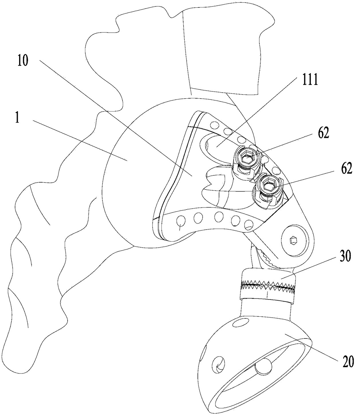
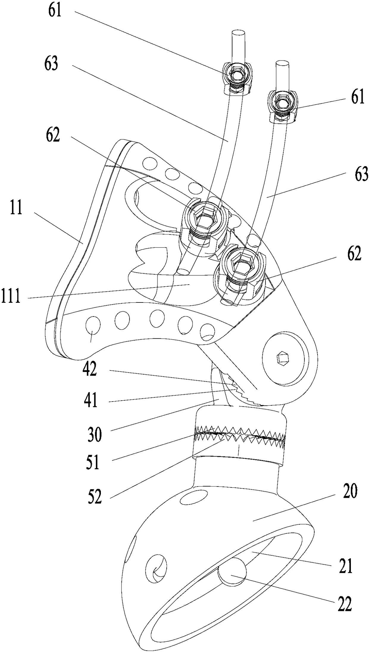
[0031] Such as figure 1 with figure 2 As shown, the hip bone prosthesis of this embodiment includes a prosthetic main body 10 , an acetabular cup 20 and a connecting device 30 . Wherein, the prosthetic main body 10 has an arched structure, and the prosthetic main body 10 includes a first end 11 and a second end, and the first end 11 is in contact with the sacrum 1; The two ends are connected.

[0032] Applying the technical solution of this embodiment, the hip bone prosthesis includes a prosthetic main body 10 , an acetabular cup 20 and a connecting device 30 . The first end 11 of the prosthetic body 10 is in contact with the sacrum 1 , and the acetabular cup 20 is in contact with the acet...


PUM


Abstract

The present invention provides a hip bone prosthesis comprising a prosthetic body having an arcuate structure, an acetabular cup and a connection device, wherein the prosthetic body comprises a first end and a second end; the first end cooperates with the sacrum in a contact way; and the acetabular cup is connected to the second end by the connection device with the adjustable position. The technical scheme of the invention can effectively solve the problems that the supporting effect of a screw and rod system is unreliable and fatigue crack is liable to cause in the prior art.

Description

technical field [0001] The invention relates to the field of medical devices, in particular to a hip bone prosthesis. Background technique [0002] The pelvis is a common site for bone tumors, and pelvic tumors can be divided into primary tumors and metastatic tumors. The former are mainly chondrosarcoma, osteosarcoma, and Ewing sarcoma, while the latter is commonly seen in bone metastases of breast cancer, kidney cancer, prostate cancer, and lung cancer. The onset of pelvic tumors is insidious and difficult to diagnose early, and the extent of invasion is often large when discovered. In addition, the anatomy around the pelvis is complex and adjacent to many important organs. The operation is difficult, with many complications, poor curative effect, and high mortality. At present, hemipelvic resection or modified hemipelvic resection and amputation are mainly used for pelvic tumors. However, the resection of any pelvic tumor will cause bone defects, which will lead to inte...

Claims


Application Information

Patent Timeline
Patent Type & Authority Patents(China)
IPC IPC(8): A61F2/32A61F2/34
CPCA61F2/30942A61F2/32A61F2/34A61F2002/30329A61F2002/30594A61F2002/30985A61F2002/3208A61F2002/3233A61F2002/3487
Inventor 郭卫王彩梅姬涛
Owner BEIJING AKEC MEDICAL
Why Eureka
Try Eureka