Bionic artificial hand

A prosthetic hand and palm technology, applied in the field of bionic prosthetic hands, can solve problems such as low practicability, increased weight, fatigue, etc., and achieve the effect of avoiding accidental touch or interference

Active Publication Date: 2016-10-26
SHENZHEN INST OF ADVANCED TECH CHINESE ACAD OF SCI
View PDF6 Cites 31 Cited by
  • Summary
  • Abstract
  • Description
  • Claims
  • Application Information

AI Technical Summary

Problems solved by technology

However, the metacarpal wrist joint of the thumb of this kind of prosthetic hand does not have an independent degree of freedom, so the internal or external rotation of the thumb needs to be assisted by manual rotation; in addition, although it realizes the bionic design in appearance and action, but Due to the heavy weight (more than 500g), it will cause a great burden to the patient, so it is not suitable for long-term wearing
[0005] At present, although the existing multi-degree-of-freedom myoelectric prosthetic hand gives each joint a degree of freedom to realize the independent movement of a single finger and joint, the number of movements can be large, but due to the large number of motors, the control system is complicated and the maintenance cost is high; in addition , due to the heavy weight, the patient is prone to soreness, fatigue and other problems after wearing it for a long time, so that it cannot be worn and used for a long time
Therefore, this kind of prosthetic hand is not only greatly reduced in practicability, but the most important point is that it is expensive, and it is difficult for ordinary patients to be accepted by ordinary families.
[0006] Secondly, the structure of myoelectric prosthetic hands on the market is made of metal for the main part, which not only increases the weight, but also uses traditional transmission methods such as gears at the joints, and the multi-stage meshing makes the transmission efficiency poor, and the torque of the motor cannot be obtained. Maximize it, and eventually lead to the need to use

Method used


Image

  • Bionic artificial hand
  • Bionic artificial hand
  • Bionic artificial hand

Examples


Embodiment Construction

[0040] The following will clearly and completely describe the technical solutions in the embodiments of the present invention with reference to the accompanying drawings in the embodiments of the present invention. Obviously, the described embodiments are only some, not all, embodiments of the present invention. Based on the embodiments of the present invention, all other embodiments obtained by persons of ordinary skill in the art without making creative efforts belong to the protection scope of the present invention.

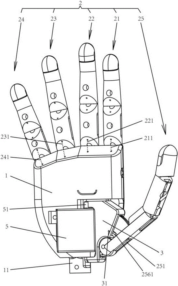
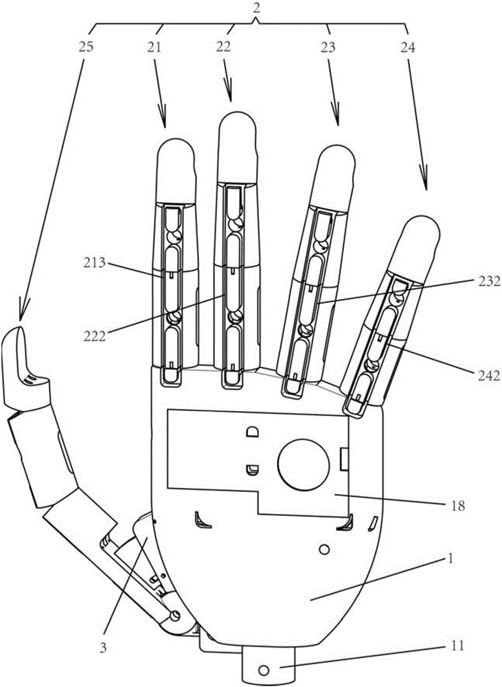
[0041] Such as figure 1 and figure 2 As shown, the present invention provides a kind of bionic prosthetic hand, and it comprises palm part 1, finger part 2 and tiger mouth part 3, wherein: finger part 2 has index finger assembly 21, middle finger assembly 22, ring finger assembly 23, little finger assembly 24 and thumb assembly 25. The index finger assembly 21, the middle finger assembly 22, the ring finger assembly 23 and the little finger assembly 24 are r...


PUM


Abstract

The invention provides a bionic artificial hand. The bionic artificial hand comprises a palm part, a finger part, and a thumb-index web part, the finger part includes a forefinger assembly, a middle finger assembly, a ring finger assembly, a little finger assembly, and a thumb assembly, wherein the forefinger assembly, the middle finger assembly, the ring finger assembly, and the little finger assembly are respectively connected to the upper end of the palm part in a detachable manner, the thumb-index web part is vertically and rotatably connected to the inside of the palm part, and the thumb assembly is detachably connected to the thumb-index web part. According to the bionic artificial hand, the thumb assembly can internally or externally rotate, and the forefinger assembly, the middle finger assembly, the ring finger assembly, the little finger assembly and the thumb assembly can be stretched or bent. The bionic artificial hand is light in weight and convenient for long time wearing and use for patients.

Description

technical field [0001] The invention relates to a prosthetic hand, in particular to a bionic prosthetic hand in the field of rehabilitation medical equipment. Background technique [0002] Myoelectric prosthetic hands can replace missing limbs and provide convenience for the daily life of disabled patients with missing upper limbs. It is one of the important research directions in the field of rehabilitation engineering. [0003] The safe proportional control myoelectric prosthetic hand in the existing products has only three fingers: thumb, index finger and middle finger, and it can only realize the single-mode action of opening or closing the hand to complete grasping; in addition, the safe proportional control myoelectric The fingers of the prosthetic hand are an integrated structure, which cannot realize coupled motion based on multi-joints. Therefore, the practicality of this product in daily life is not high. [0004] In the existing products, there is also a prosthe...

Claims


Application Information

Patent Timeline
IPC IPC(8): A61F2/54A61F2/58A61F2/70
CPCA61F2/54A61F2/583A61F2/586A61F2/68A61F2002/701A61F2/58A61F2/70
Inventor 景晓蓓雍旭徐睿郑悦田岚张浩诗李向新李光林
Owner SHENZHEN INST OF ADVANCED TECH CHINESE ACAD OF SCI
Why Eureka
Try Eureka