
Organic waste gas treatment method

A technology of organic waste gas and treatment methods, which is applied in the direction of gas treatment, separation methods, chemical instruments and methods, etc. It can solve the problems of substandard exhaust gas, prolonged adsorption time, and impact on environmental quality, so as to prevent cross-gas and improve drying effect , The effect of short desorption time

Inactive Publication Date: 2016-10-26
清本环保工程(杭州)有限公司
View PDF6 Cites 1 Cited by
  • Summary
  • Abstract
  • Description
  • Claims
  • Application Information

AI Technical Summary

Problems solved by technology

[0003] 1. Use low-pressure saturated steam for desorption, and the desorption efficiency is 98% after desorption for 30 minutes. The residual organic matter is purged and discharged, resulting in the initial discharge gas not meeting the standard; if the desorption time continues to increase, the desorption effect will not increase. Obviously, if the desorption efficiency is 99% after 60 minutes of desorption, at the same time, the increase of desorption time will lead to the inability to switch the adsorption tank, and the prolongation of the adsorption time will lead to the emission of purified tail gas in the later stage of adsorption not up to the standard;
[0004] 2. When the desorption is completed, the adsorber is filled with a large amount of steam, and the residual steam is blown out during the purging process, resulting in a large amount of liquid and white smoke in the exhaust pipe and chimney, which not only affects the service life of the chimney, but also affects the environmental quality;
[0005] 3. The best adsorption temperature of the adsorption material is 20-40°C, high temperature is not conducive to the adsorption of organic matter, and when the desorption is completed, the temperature of the adsorber is about 100°C, and the organic matter cannot be adsorbed by the adsorbent

Method used


Image

  • Organic waste gas treatment method

Examples


Embodiment 1

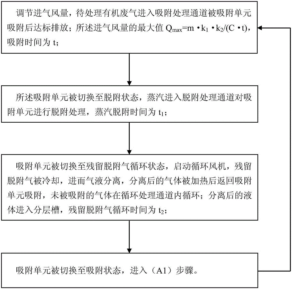
[0031] figure 1 The flow chart of the organic waste gas treatment method of this embodiment is schematically given, such as figure 1 As shown, the organic waste gas treatment method includes the following steps:

[0032] (A1) Adjust the intake air volume, and the organic waste gas to be treated enters the adsorption treatment channel and is adsorbed by the adsorption unit before reaching the discharge standard; the maximum value of the intake air volume Q max =m·k 1 ·K 2 / (C·t), where m is the effective adsorbent mass, k 1 Is the dynamic adsorption capacity, k 2 To design the surplus coefficient, C is the concentration of organic matter in the organic waste gas to be treated, and t is the adsorption time;

[0033] (A2) The adsorption unit is switched to the desorption state, the steam enters the desorption treatment channel to perform desorption treatment on the adsorption unit, and the steam desorption time is t 1 ;

[0034] (A3) The adsorption unit is switched to the residual de...

Embodiment 2

[0052] Application of the organic waste gas treatment method according to Example 1 in the treatment of toluene tail gas. In this application example, the cooler is a surface cooler. After the surface cooler is cooled, the temperature of the residual desorption gas is reduced to 10-30°C; after cooling, it is further separated by gas and liquid, and the relative humidity of the separated gas reaches 100%. It is heated by the reheating air-conditioning box, and the temperature is increased by 5-15℃ to reduce the relative humidity of the gas; the pipeline between the surface cooler, the gas-liquid separator and the stratified tank is equipped with a liquid seal structure ≥500mm; The inlet valve, the first outlet valve, the second inlet valve, the second outlet valve, the third inlet valve and the third outlet valve are all pneumatic valves or electric automatic valves, which are switched through the PLC control module, which is set The working time of the adsorber in different sta...


PUM


Abstract

The invention relates to an organic waste gas treatment method. The organic waste gas treatment method comprises the following steps: (A1) adjusting intake air volume, feeding organic waste gas to be treated into an adsorption treatment channel, adsorbing the organic waste gas to be treated by using an adsorption unit, and discharging the organic waste gas after the organic waste gas reaches the standard, wherein the maximum value of the intake air volume is as follows: Qmax= m.k1.k2 / (C.t); (A2) switching the adsorption unit to be in a desorption state, and feeding steam into a desorption treatment channel to carry out desorption treatment; (A3) switching the adsorption unit to be in a residual desorption gas circulating state, starting a circulating fan, cooling residual desorption gas so that gas-liquid separation is realized, heating separated gas and then returning the heated separated gas to the adsorption unit for adsorption, and circulating the gas which is not adsorbed in a circulation treatment channel, and feeding the separated liquid into a layering groove; (A4) switching the adsorption unit to be in an adsorption state, and entering the step (A1). The organic waste gas treatment method has the advantages of safety and reliability, circulating cooling and adsorption of residual desorption gas, discharge of tail gas with standard level and the like.

Description

Technical field [0001] The invention relates to the field of waste gas treatment and recovery, in particular to a method for treating organic waste gas by circulating cooling and adsorbing residual desorption gas after steam desorption. Background technique [0002] The method of temperature swing adsorption, desorption and regeneration after adsorption has been used to treat organic waste gas for many years, and it is especially suitable for industrial exhaust gas with high air volume and low concentration. Desorption regeneration includes steam desorption, hot nitrogen desorption and vacuum desorption. Among them, steam desorption is widely used because of its good desorption effect, low energy consumption, and convenience in public projects. However, the temperature swing adsorption steam desorption has the following defects in the application process: [0003] 1. Using low-pressure saturated steam for desorption, the desorption efficiency is 98% after 30 minutes of desorption,...

Claims


Application Information

Patent Timeline
Patent Type & Authority Applications(China)
IPC IPC(8): B01D53/04
CPCB01D53/0407B01D53/0454B01D2259/4009
Inventor 王功换刘硕蔡炳良孙瑀廖丹丹林永辉
Owner 清本环保工程(杭州)有限公司
Learn More