Tensioning device for a stirred ball mill with a belt or chain drive, and stirred ball mill

A technology of agitating ball milling and tensioning device, applied in the direction of transmission, belt/chain/gear, mechanical equipment, etc.

Active Publication Date: 2016-10-26
耐驰精细研磨技术有限公司
View PDF6 Cites 1 Cited by
  • Summary
  • Abstract
  • Description
  • Claims
  • Application Information

AI Technical Summary

Problems solved by technology

The problem with the known system is, in particular, that two persons are respectively required to adjust the belt tension, since one person has to adjust and maint

Method used


Image

  • Tensioning device for a stirred ball mill with a belt or chain drive, and stirred ball mill
  • Tensioning device for a stirred ball mill with a belt or chain drive, and stirred ball mill
  • Tensioning device for a stirred ball mill with a belt or chain drive, and stirred ball mill

Examples


Embodiment Construction

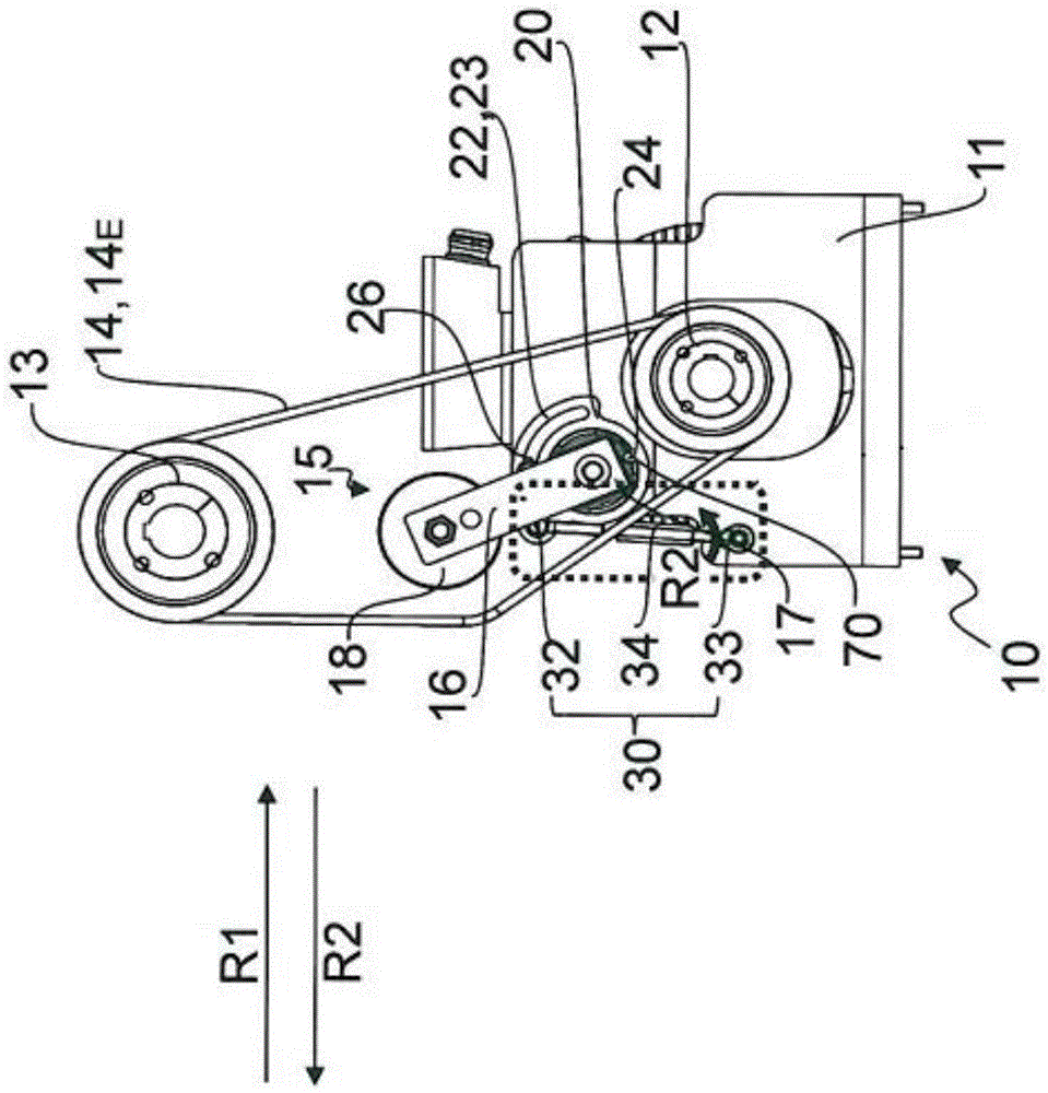
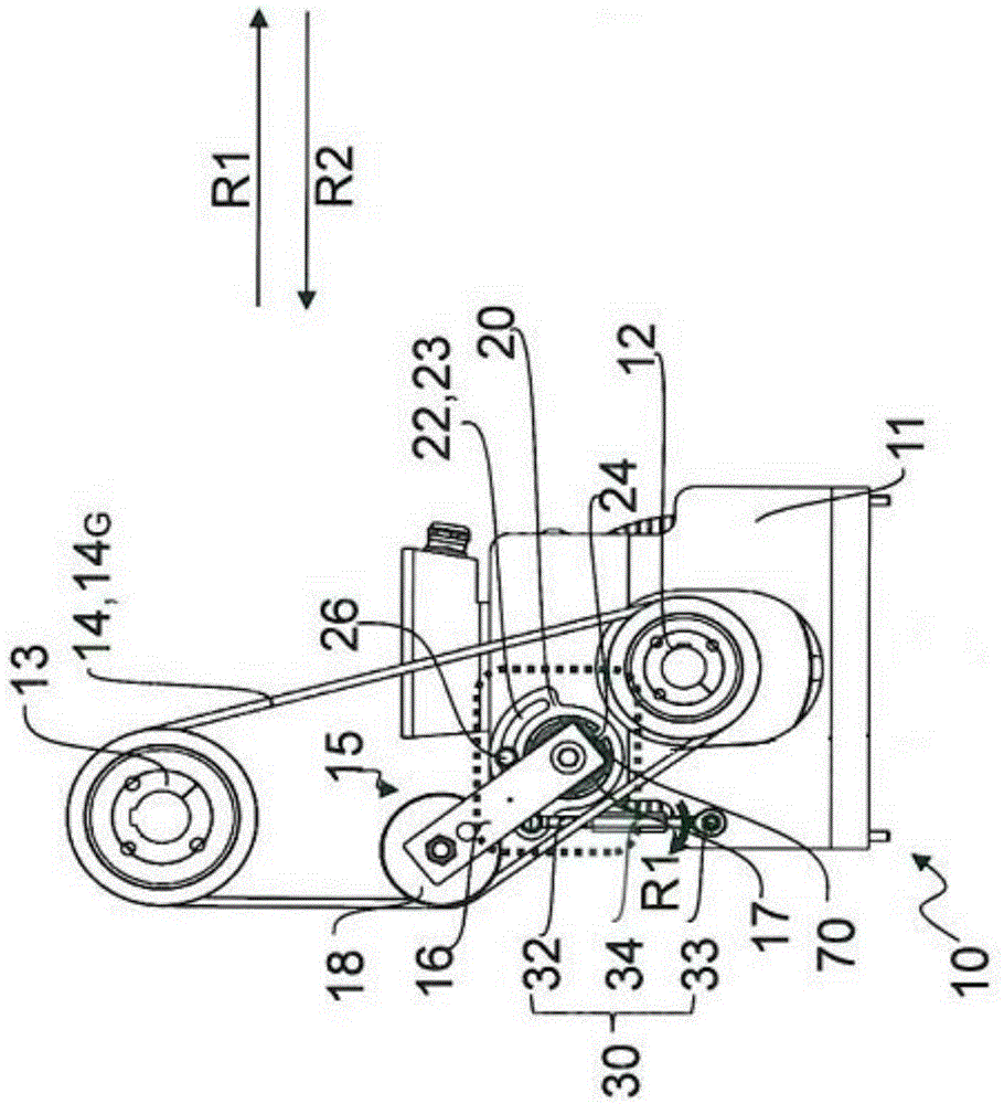
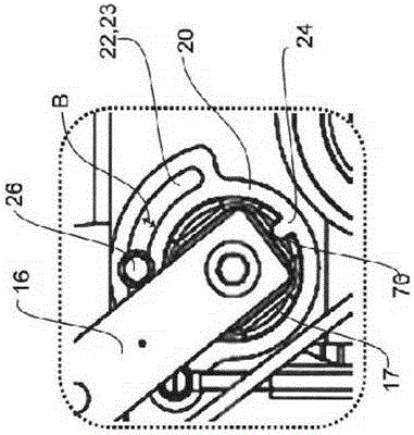
[0035] figure 1 A first embodiment of an agitator ball mill 1 a with a tensioning device 5 a according to the known prior art is shown. The stirring shaft 3a of the stirring ball mill 1a is driven by the drive shaft 2a via a chain or a belt 4a. A tensioning device 5 a is provided for adjusting the required belt tension of the belt 4 a. The tensioning device comprises a tensioning rod 6a with a tensioning wheel 8a arranged at a tensioning seat 7a. In order to adjust the tension of the belt 4a, the user must first loosen fastening means (not shown) at the tensioning seat 7a in order to be able to adjust the tensioning seat. The user must then place a tool on the clamping seat 7a and turn the clamping seat with the tool. The rotational movement is transmitted via the tensioning rod 6a to the tensioning pulley 8a, whereby the tensioning pulley presses on the belt 4a more or less depending on the direction of rotation. After the desired belt tension has been achieved, the faste...


PUM


Abstract

The invention relates to a tensioning device for the belt or chain drive of a stirred ball mill and to a stirred ball mill. The tensioning device comprises a tensioning lever which is arranged on a rotatable tensioning foot and which comprises a tensioning wheel. A rotatable adjusting disk with a guide contour is arranged on the rotatable tensioning foot. The position of the adjusting disk can be fixed on the machine housing of the stirred ball mill by means of a securing means paired with the guide contour of the adjusting disk. The tensioning device further comprises a longitudinally variable tensioning element for rotating the adjusting disk relative to the machine housing of the stirred ball mill.

Description

technical field [0001] The invention relates to a tensioning device for an agitator ball mill with a belt drive or a chain drive and to an agitator ball mill according to the features of the preambles of claims 1 and 12 . Background technique [0002] The invention relates to an agitating ball mill, wherein the agitating shaft of the agitator is driven by a belt drive or a chain drive. Usually a transmission is used for driving the stirrer, which requires a lot of space and is lubricated with oil, which can lead to contamination due to spillage of the transmission lubricating oil. Furthermore, a correspondingly separately designed gear must be used for changing the rotational speed, which results in high costs. [0003] In order to reduce costs, it is known to operate the mixer shaft in a rotary drive via a belt drive, in particular a gear drive or a V-belt drive. [0004] DE29710013U1 describes a mixer in which the drive is a belt drive. In this document a belt tension a...

Claims


Application Information

Patent Timeline
IPC IPC(8): B02C17/16B02C17/18B02C17/24
CPCB02C17/16B02C17/18B02C17/24F16H7/1281B02C17/163
Inventor M·贝茨尔P·拉特
Owner 耐驰精细研磨技术有限公司
Why Eureka
Try Eureka