Riveting mechanism of riveting machine

The technology of a riveting mechanism and a riveting machine, which is applied in the field of mechanical automation, can solve the problems affecting the service life of products, the complex structure of the riveting mechanism, and the low work efficiency of workers, and achieves the effects of high work efficiency, good riveting effect and simple structure.

Active Publication Date: 2016-10-26
湖南哈工机器人研究院有限公司
View PDF8 Cites 7 Cited by
  • Summary
  • Abstract
  • Description
  • Claims
  • Application Information

AI Technical Summary

Problems solved by technology

[0002] In the previous riveting of workpieces, it was generally operated manually, but manual operation is prone to errors, which directly affects the service life of the product, and the work efficiency of the workers is low, which increases the production cost. However, the riveting mechanism of the existing riveting machine The structure is complicated, the operation is inconvenient, and the cost is high. In view of this, it is necessary to improve the riveting mechanism of the existing riveting machine

Method used


Image

  • Riveting mechanism of riveting machine
  • Riveting mechanism of riveting machine
  • Riveting mechanism of riveting machine

Examples


Embodiment Construction

[0011] The preferred embodiments of the present invention will be described in detail below in conjunction with the accompanying drawings, so that the advantages and features of the invention can be more easily understood by those skilled in the art, so as to define the protection scope of the present invention more clearly.

[0012] see Figures 1 to 5 , the embodiment of the present invention includes:

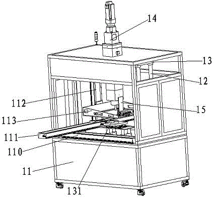
[0013] A riveting mechanism of a riveting machine, the riveting mechanism of the riveting machine includes a riveting frame 11, two corresponding supporting columns 12 are installed on the opposite sides of the working table of the riveting frame 11, and four supporting columns 12 The upper end is fixed with a press fixed plate 13, and a longitudinal press 14 is installed on the press fixed plate 13. The upper part of the press 14 passes through the top surface of the riveting frame 11, and the lower part of the press 14 passes through the press fixed plate 13 And the botto...


PUM


Abstract

The invention discloses a riveting mechanism of a riveting machine. The riveting mechanism of the riveting machine comprises a riveting rack. The two opposite sides of a worktable top of the riveting rack are each provided with two corresponding supporting pillars. A pressing machine fixing plate is fixed to the upper ends of the four supporting pillars. A longitudinal pressing machine is installed on the pressing machine fixing plate. The upper portion of the pressing machine penetrates the top face of the riveting rack, and the lower portion of the pressing machine penetrates the pressing machine fixing plate and is fixed to the vertical edge of an L-shaped air cylinder installation plate. A longitudinal displacement sliding table air cylinder is installed on the lower plane of the transverse edge of the L-shaped air cylinder installation plate. A rivet discharging sliding table air cylinder perpendicular to a sliding table of the displacement sliding table air cylinder is installed on the sliding table of the displacement sliding table air cylinder. The output end of a sliding table of the rivet discharging sliding table air cylinder is provided with a rivet discharging connecting block. The end face of the rivet discharging connecting block is provided with two pairs of rivet clamping claws through rivet discharging guide rods. By means of the above manner, the riveting mechanism is convenient to operate, long in service life and capable of greatly improving the production efficiency.

Description

technical field [0001] The invention relates to the field of mechanical automation, in particular to a riveting mechanism of a riveting machine. Background technique [0002] In the previous riveting of workpieces, it was generally operated manually, but manual operation is prone to errors, which directly affects the service life of the product, and the work efficiency of the workers is low, which increases the production cost. However, the riveting mechanism of the existing riveting machine The structure is complicated, the operation is inconvenient, and the cost is high. In view of this, it is necessary to improve the riveting mechanism of the existing riveting machine. Contents of the invention [0003] The technical problem mainly solved by the present invention is to provide a riveting mechanism of a riveting machine, which has simple structure, convenient operation, good riveting effect, high work efficiency, less workpiece wear, long service life of the machine and ...

Claims


Application Information

Patent Timeline
Patent Type & Authority Applications(China)
IPC IPC(8): B21J15/10B21J15/38
CPCB21J15/10B21J15/38
Inventor 蒯斌
Owner 湖南哈工机器人研究院有限公司
Why Eureka
Try Eureka