Vertical type electromagnetic braking device for controlling flow of molten steel in continuous casting crystallizer

A technology of continuous casting crystallizer and electromagnetic braking, which is applied in the field of continuous casting to achieve the effect of improving quality

Active Publication Date: 2016-10-26
NORTHEASTERN UNIV LIAONING
View PDF7 Cites 8 Cited by
  • Summary
  • Abstract
  • Description
  • Claims
  • Application Information

AI Technical Summary

Problems solved by technology

[0013] Aiming at the problems existing in the prior art, the present invention provides a new and improved vertical electromagnetic brake device for controlling the flow of molten steel in the continuous casting mold, which preferentially suppresses the impact of the liquid steel flowing out of the nozzle on the side of the mold and the bending of the mold. While the molten steel surface flows on the lunar surface, it can control the molten steel flow in the central area of ​​the mold, avoiding the situation that the surface flow rate of the molten steel in the central area of ​​the mold is too low and the impact depth of the molten steel under the reflow is too deep, so as to inhibit the steel Fluctuations and slag entrainment on the liquid surface promote the floating of heterogeneous substances such as slag inclusions and air bubbles, so that the metallurgical effect of electromagnetic braking is less affected by changes in process parameters

Method used


Image

  • Vertical type electromagnetic braking device for controlling flow of molten steel in continuous casting crystallizer
  • Vertical type electromagnetic braking device for controlling flow of molten steel in continuous casting crystallizer
  • Vertical type electromagnetic braking device for controlling flow of molten steel in continuous casting crystallizer

Examples


Embodiment 1

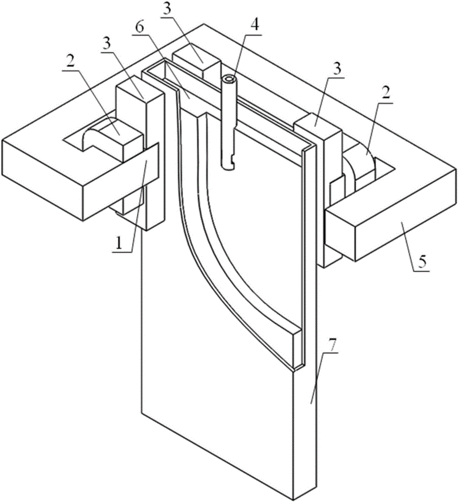
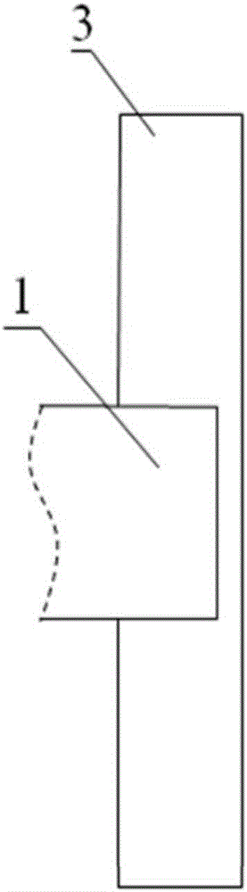
[0087] In this example, using figure 1 In the vertical electromagnetic braking device shown, the vertical magnetic pole 3 and the horizontal magnetic pole 1 adopt the connection method in Figure 3(a), and the vertical magnetic pole 3 covers the side of the mold 7 in height from the molten steel surface 6 area to the intrusive nozzle 4 The impact point of the molten steel and the area below the horizontal magnetic pole 1, the cross-sectional size of the crystallizer 7 is 300mm×50mm, and the height of the vertical magnetic pole 3 is 240mm.

[0088] The currents of 700A and 1050A are respectively applied to the excitation coil 2 of the horizontal magnetic pole 1, and the magnetic field distribution diagram of the vertical magnetic pole center along the height direction of the center section of the side of the crystallizer is as follows Figure 7 shown.

[0089] Depend on Figure 7 It can be seen that with the increase of current intensity, the magnetic induction intensity gradu...

Embodiment 2

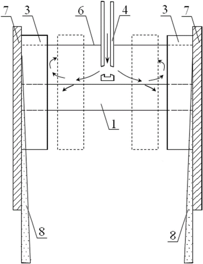
[0091] In this example, using figure 1 In the vertical electromagnetic braking device shown, in order to observe the fluctuation of the liquid level in the crystallizer 7 more intuitively, the test object is the metal liquid of the low melting point alloy SnPbBi; the vertical magnetic pole 3 and the horizontal magnetic pole 1 adopt the Connection method, the vertical magnetic pole 3 covers the side of the mold 7 in height, from the molten steel surface 6 area to the impact point of the intrusive nozzle 4 outflowing molten steel and the area under the horizontal magnetic pole 1, the thickness of the mold 7 is 100mm, and the mold The half width of 7 is 600mm, the height of vertical magnetic pole 3 is 440mm, the inclination angle of the side hole of intrusive nozzle 4 is -15°, the intrusion depth of intrusive nozzle 4 is 100mm, and the casting speed is 1.27m / min.

[0092] Apply current to the excitation coil 2 of the horizontal magnetic pole 1, so that a magnetic field of about 0...

Embodiment 3

[0095] In this example, using figure 1 In the vertical electromagnetic braking device shown, the vertical magnetic pole 3 and the horizontal magnetic pole 1 adopt the connection method in Figure 3(c), then the height of the vertical magnetic pole 3 below the horizontal magnetic pole 1 is 0mm, and the vertical magnetic pole 3 covers the height The side of the mold 7 is from the area 6 of the molten steel surface to the impact point of the molten steel flowing out of the intrusive nozzle 4 and the area above the horizontal magnetic pole 1. The cross-sectional size of the mold 7 is 1400mm×230mm, and the inclination angle of the side hole of the intrusive nozzle 4 is - 15°, the penetration depth of the intrusive nozzle 4 is 170mm, and the casting speed is 1.6m / min.

[0096] A current of 850A is applied to the excitation coil 2 of the horizontal magnetic pole 1, and the internal magnetic field distribution diagram of the molten steel in the mold 7 is as follows Figure 9 As shown ...


PUM

PropertyMeasurementUnit
widthaaaaaaaaaa
magnetic flux densityaaaaaaaaaa

Abstract

The invention relates to a vertical type electromagnetic braking device for controlling flow of molten steel in a continuous casting crystallizer. The vertical type electromagnetic braking device comprises one or two pairs of horizontal magnetic poles, a magnet exciting coil, two pairs of vertical type magnetic poles and a magnet yoke; when one pair of horizontal magnetic poles are arranged, the horizontal magnetic poles are located below an intrusive type water opening and distributed along a wide face of the crystallizer; when two pairs of horizontal magnetic poles are arranged, the horizontal magnetic poles are marked as upper horizontal magnetic poles and lower horizontal magnetic poles, the lower horizontal magnetic poles are located below the intrusive type water opening and distributed along the wide face of the crystallizer, and the upper horizontal magnetic poles are located nearby the surface of the molten steel in the crystallizer and distributed along the wide face of the crystallizer; the two pairs of vertical type magnetic poles are distributed nearby areas of the two side faces of the crystallizer and intersect with the one or two pairs of horizontal magnetic poles; the magnet exciting coil and the magnet yoke are matched with the horizontal magnetic poles to be installed, a current is exerted through the magnet exciting coil, and a steady-state magnetic field is generated between the horizontal magnetic poles and the vertical type magnetic poles; and when passing through the steady-state magnetic field, the molten steel flowing in the crystallizer bears electromagnetic force opposite to the flowing direction of the molten steel, and flow of the molten steel in the crystallizer is controlled through the electromagnetic force.

Description

technical field [0001] The invention belongs to the technical field of continuous casting, in particular to a vertical electromagnetic braking device for controlling the flow of molten steel in a continuous casting crystallizer. Background technique [0002] In the process of continuous casting, molten steel enters the crystallizer through the submerged nozzle at a certain jet angle, and the molten steel flowing out from the submerged nozzle will hit the side area of ​​the mold at a certain flow rate, thereby forming up-flow and down-flow Reflux. [0003] The molten steel flowing back from above will impact the surface of the molten steel in the mold, thereby causing liquid level fluctuations, especially aggravating the liquid level fluctuations near the meniscus on the side of the mold, and easily causing slag entrainment. [0004] The penetration depth of molten steel flowing back from the bottom is relatively large, which will bring heterogeneous substances such as inclu...

Claims


Application Information

Patent Timeline
Patent Type & Authority Applications(China)
IPC IPC(8): B22D11/16B22D11/11
CPCB22D11/11B22D11/16B22D11/115B22D11/186B22D11/18
Inventor 王恩刚李壮许琳李菲邓安元张兴武张林
Owner NORTHEASTERN UNIV LIAONING
Why Eureka
Try Eureka