Combined type automatic feeding machine tool with loading device

An automatic feeding and combined technology, applied in milling machines, milling machine equipment, manufacturing tools, etc., can solve the problems of non-detachable hoppers, cumbersome disassembly and maintenance, and difficulty in automatic loading and unloading of materials, so as to achieve industrialized continuous production and convenient replacement Effect

Inactive Publication Date: 2016-10-26
申清章
View PDF9 Cites 1 Cited by
  • Summary
  • Abstract
  • Description
  • Claims
  • Application Information

AI Technical Summary

Problems solved by technology

Since the hopper of this kind of automatic feeding device cannot be disassembled, and there is only a single hopper, when the hopper is deformed due to bumping, it is easy to jam the main workpiece, and the disassembly and maintenance are more cumbersome; in addition, it is difficult to realize industrialized automatic loading and unloading of materials with this single fixed hopper

Method used


Image

  • Combined type automatic feeding machine tool with loading device
  • Combined type automatic feeding machine tool with loading device
  • Combined type automatic feeding machine tool with loading device

Examples


Embodiment 1)

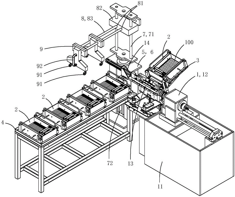
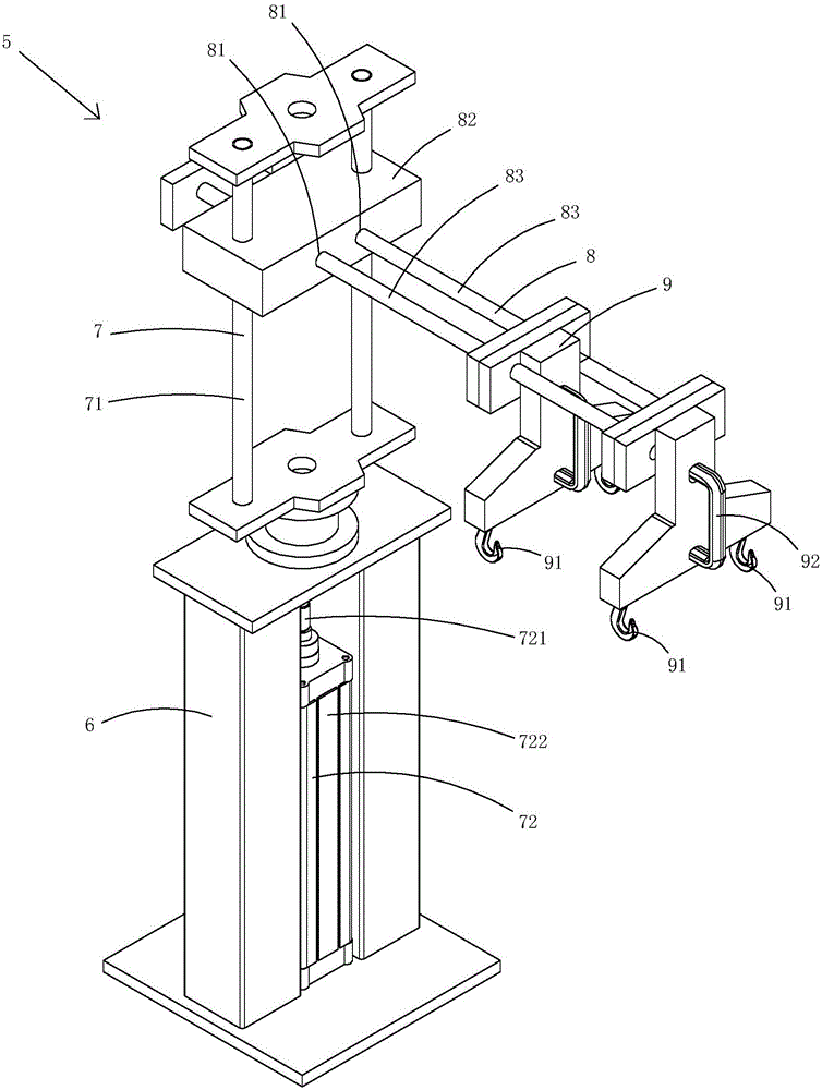
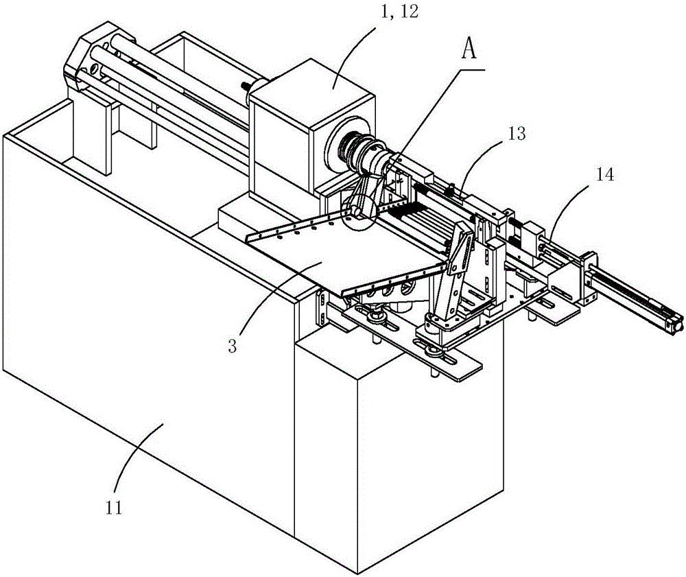
[0015] Figure 1 to Figure 8 A specific embodiment of the invention is shown in which, figure 1 It is a schematic diagram of a three-dimensional structure of the present invention; figure 2 for figure 1 A schematic diagram of a three-dimensional structure of the feeding device in the machine tool shown; image 3 for figure 1 A schematic diagram of the three-dimensional structure of the machine tool shown after removing the feeding device, unloading rack and hopper; Figure 4 for image 3 Partial enlarged schematic diagram of A; Figure 5 for figure 1 A schematic diagram of a three-dimensional structure of the hopper in the machine tool shown; Figure 6 for Figure 5 A top view of the hopper shown; Figure 7 for Figure 5 A schematic cross-sectional structure of the hopper shown; Figure 8 for Figure 7 A schematic diagram of the structure of the shown hopper resting on the hopper support.

[0016] Present embodiment is a kind of combined automatic feeding machine...


PUM


Abstract

The invention discloses a combined type automatic feeding machine tool with a loading device. The combined type automatic feeding machine tool comprises a machine tool body, hoppers, a hopper support, an accommodating frame and the loading device. The hopper support is arranged on the machine tool body, and the loading device is used for transferring the hoppers on the accommodating frame to the hopper support; the loading device comprises a loading support, a lifting mechanism, a translation mechanism and a hooking mechanism, the lifting mechanism is rotationally arranged on the loading support, the translation mechanism can reciprocate in the horizontal direction, and the hooking mechanism is used for hooking hanging portions of the hoppers; the lifting mechanism comprises lifting rods and a driving mechanism, and the lifting rods can be driven by the driving mechanism to move up and down and are rotationally arranged on the loading support; the translation mechanism comprises a positioning plate and slide rods, the positioning plate is arranged on the lifting rods, horizontal slide holes are formed in the positioning plate, and the slide rods can reciprocate along the horizontal slide holes; the hooking mechanism comprises hooks, and the hooks are arranged on the slide rods. The combined type automatic feeding machine tool has the advantages that the combined type automatic feeding machine tool comprises the loading device for transferring the hoppers on the accommodating frame to the hopper support, accordingly, the hoppers can be conveniently replaced, and industrial continuous production can be facilitated.

Description

technical field [0001] The invention belongs to the technical field of machine tool structure design, and in particular relates to a combined automatic feeding machine tool with a feeding device. Background technique [0002] In existing machine tools, its automatic feeding device generally includes a hopper fixedly arranged on the machine tool body. The hopper has a fixed discharge port. During work, the workpieces in the hopper fall from the discharge port to preset positions in sequence, so that each workpiece For processing. Since the hopper of this kind of automatic feeding device cannot be disassembled, and there is only a single hopper, when the hopper is deformed due to bumping, it is easy to get stuck in the main workpiece, and disassembly and maintenance are more cumbersome; in addition, it is difficult to realize industrial automatic loading and unloading of materials with this single fixed hopper. Contents of the invention [0003] The object of the present in...

Claims


Application Information

Patent Timeline
Patent Type & Authority Applications(China)
IPC IPC(8): B23Q7/10B23C1/02
CPCB23C1/02B23Q7/00B23Q7/005B23Q7/06B23Q7/10B23Q7/106B23Q7/1415B23Q7/1494H04N1/00519H04N1/00557H04N1/00559H04N1/04
Inventor 申俊
Owner 申清章
Why Eureka
Try Eureka