Measurement device for tail spatial position of robot

A technology of spatial position and measuring devices, applied in the direction of manipulators, manufacturing tools, etc., can solve the problems of high cost of vision and laser measurement technology, inapplicability of multi-degree-of-freedom robots, and high requirements for the cleanliness of the measurement environment, which is conducive to promotion and structure Simple, low-cost effect

Inactive Publication Date: 2016-10-26
SHANGHAI UNIV
View PDF7 Cites 6 Cited by
  • Summary
  • Abstract
  • Description
  • Claims
  • Application Information

AI Technical Summary

Problems solved by technology

[0003] At present, the spatial position of the robot end generally includes theodolite, three-coordinate measuring instrument, visual inspection technology, and laser tracking technology, but the steps of using theodolite are complicated and cumbersome, and the three-coordinate measuring instrument has strict requirements on the measurement environment and is not suitable for multi-degree-of-freedom robots. Laser measurement technology is expensive and requires high cleanliness of the measurement environment

Method used


Image

  • Measurement device for tail spatial position of robot
  • Measurement device for tail spatial position of robot
  • Measurement device for tail spatial position of robot

Examples


Embodiment Construction

[0015] The present invention will be further described below in conjunction with the drawings.

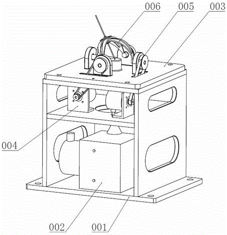
[0016] Such as figure 1 As shown, a device for measuring the spatial position of the end of a robot includes a base 001, a wire-pulling encoder 002, a transition mounting plate 003, an encoder assembly 004, a timing belt 005, and a follow-up pointing mechanism 006. The wire-pulling encoder 002 is screwed Installed at the bottom of the base 001, the transition mounting plate 003 is installed on the top of the base 001 by screws, the two encoder components 004 are installed in the middle of the base 001 by screws, and the follow-up pointing mechanism 006 is through deep groove ball bearings 011 It is installed in the four circular holes of the transitional mounting plate 003, and the follow-up pointing mechanism 006 is connected to the encoder assembly 004 through a timing belt 005.

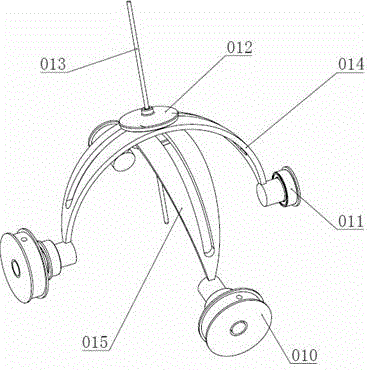
[0017] Such as image 3 As shown, the follower pointing mechanism 006 includes an outer arc follower 014...


PUM


Abstract

The invention relates to a measurement device for the tail spatial position of a robot. The measurement device comprises a base, a stay wire encoder, a transitional mounting plate, encoder assemblies, synchronous belts and follow-up pointing mechanisms, wherein the stay wire encoder is mounted on the bottom of the base through screws; the transitional mounting plate is mounted on the top of the base through screws; the two encoder assemblies are mounted in the middle of the base through screws; and the follow-up pointing mechanisms are mounted in four round holes of the transitional mounting plate through deep groove ball bearings and connected with the encoder assemblies through the synchronous belts. The measurement device is high in precision, convenient to operate and low in cost, and has a low requirement for the measurement environment.

Description

Technical field [0001] The invention discloses a device for measuring the space position of the end of a robot, and relates to the field of measuring the end position of the robot. Background technique [0002] The robot terminal space position measuring device is used for the calibration of the positioning accuracy of the robot when it leaves the factory, and the detection of the speed and acceleration during the movement. After measuring the end position, speed and acceleration, and calibrating the robot, the positioning accuracy of the robot can be greatly improved, and the working efficiency of the robot can be improved. [0003] At present, the space position of the robot end generally includes theodolite, three-coordinate measuring instrument, visual inspection technology, and laser tracking technology. However, the use of theodolite is complicated and cumbersome. The three-coordinate measuring instrument has strict requirements for the measurement environment and is not suit...

Claims


Application Information

Patent Timeline
Patent Type & Authority Applications(China)
IPC IPC(8): B25J19/00
CPCB25J19/0095
Inventor 侯涛匡志鹏文静何永义
Owner SHANGHAI UNIV
Why Eureka
Try Eureka