Concrete stirring device
A mixing device and concrete technology, which is applied in the direction of cement mixing device, clay preparation device, unloading device, etc., can solve the problems of low mixing efficiency, uneven mixing, easy damage to mixing parts, etc., and achieve good mixing effect and uniform mixing Effect
- Summary
- Abstract
- Description
- Claims
- Application Information
AI Technical Summary
Problems solved by technology
Method used
Image

Examples
Embodiment Construction
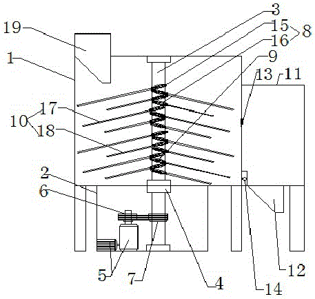
[0011] Such as figure 1 A concrete mixing device shown includes a concrete mixing chamber 1, and a motor chamber 2 arranged below the concrete mixing chamber; and a transmission shaft 3 passing through the motor chamber and the concrete mixing chamber; the top of the transmission shaft 3 is installed on the The top of the concrete mixing chamber 1; the bottom of the transmission shaft 3 is installed on the bottom of the motor chamber 2 through a bearing; the motor chamber 2 and the concrete mixing chamber 3 are provided with a bearing 4 at the place where the transmission shaft 3 passes; the motor chamber 1 is provided with Power mechanism 5; the output end of the power mechanism 5 is provided with a first pulley 6; the transmission shaft 3 is provided with a second pulley 7 in the motor room; the first pulley 6 and the second pulley 7 pass through Belt installation; the outer wall of the transmission shaft 3 is provided with a plurality of inclined non-return thread chutes 8 ...
PUM
 Abstract
Description
Claims
Application Information
 - R&D
- Intellectual Property
- Life Sciences
- Materials
- Tech Scout
- Unparalleled Data Quality
- Higher Quality Content
- 60% Fewer Hallucinations
Browse by: Latest US Patents, China's latest patents, Technical Efficacy Thesaurus, Application Domain, Technology Topic, Popular Technical Reports.
© 2025 PatSnap. All rights reserved.Legal|Privacy policy|Modern Slavery Act Transparency Statement|Sitemap|About US| Contact US: help@patsnap.com