Flying system for unmanned aerial vehicle

A technology of unmanned aerial vehicles and flying devices, which is applied in the field of unmanned aerial vehicles to achieve the effects of fast flight speed, long battery life, and convenient take-off and landing

Inactive Publication Date: 2016-10-26
TIANJIN AURORA UNMANNED AEAIL SYST TECH CO LTD
View PDF12 Cites 18 Cited by
  • Summary
  • Abstract
  • Description
  • Claims
  • Application Information

AI Technical Summary

Problems solved by technology

[0007] The object of the present invention is to propose unmanned aerial vehicle flight system, by the fixed-wing flying device and the variable-rotating-wing flying device of rotation direction, solve the problem that when the prior art fixed-wing flying device and rotating-wing flying device have both, the rotating-wing flying device is in normal flight. It becomes a problem of resistance, and has the advantages of both fixed-wing and rotary-wing flying devices, with convenient take-off and landing, long battery life, and fast flight speed

Method used


Image

  • Flying system for unmanned aerial vehicle
  • Flying system for unmanned aerial vehicle

Examples


Embodiment 1

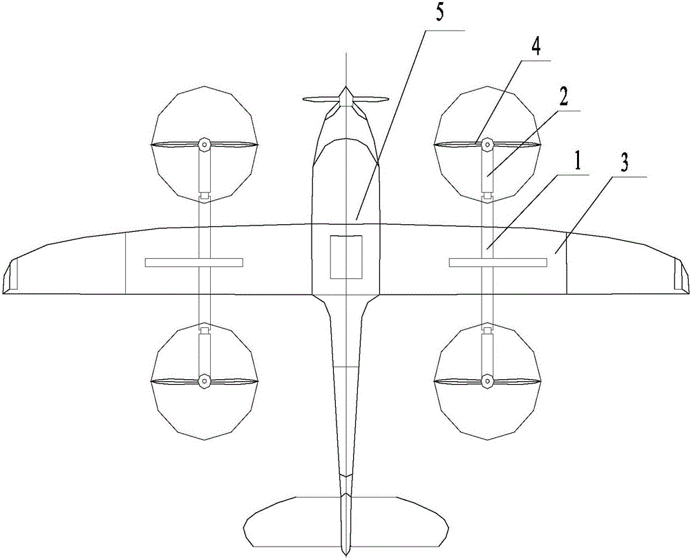
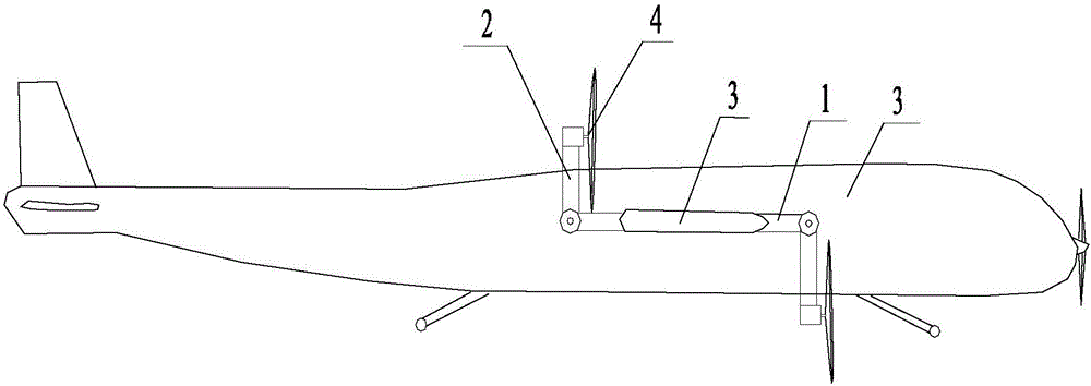
[0026] A drone flight system such as Figure 1-2 As shown, it includes: a fixed-wing flying device and a rotary-wing flying device with variable rotation direction, and a control system that is respectively connected to the fixed-wing flying device and the rotating-wing flying device. The extension shaft 1, the tilting assembly 2 rotatably connected to at least one end of the extension shaft 1, and the electric rotor mechanism 4 connected to the outer end of the tilting assembly 2, the electric rotor mechanism 4 is connected to the tilting assembly 2 Driven by the drone, it forms a set angle with the horizontal plane to match the take-off, landing and flight of the drone. The rotation of the tilting assembly 2 drives the electric rotor mechanism 4 to change between the two directions of the horizontal plane and the vertical plane. When the electric rotor mechanism 4 rotates in the horizontal plane, the rapid take-off and landing of the UAV is realized; when the When the elect...

Embodiment 2

[0032] The difference from Embodiment 1 is that there is one extension shaft 1, the extension shaft 1 is arranged on the central axis of the fuselage, and the extension shaft 1 is parallel to or perpendicular to the central axis of the fuselage.

[0033] Only one end of the extension shaft 1 may be connected to the tilting assembly 2, or both ends of the extension shaft 1 may be connected to the tilting assembly 2. When only one end of the extension shaft 1 is connected to the tilting assembly 2, The tilting assembly 2 can be parallel to the horizontal plane when the UAV takes off and lands, so as to drive the electric rotor mechanism 4 to be parallel to the horizontal plane; it is also possible to turn the tilting assembly 2 clockwise downward on the extension shaft 1 when the UAV is flying horizontally Rotate downward or upward above the extension shaft 1 to drive the electric rotor mechanism 4 to rotate in the vertical plane to provide horizontal thrust for the horizontal di...

Embodiment 3

[0037] The difference from Embodiment 1 and Embodiment 2 is that the length of the tilting assembly 2 can be adjusted to meet the requirements of the rotating space between the tilting assembly 2 and the electric rotor mechanism 4, and the height difference between the electric rotor mechanism 4 set up.

[0038] Or the wing length of the electric rotor mechanism 4 can be adjusted to meet the requirement of the rotation space of the tilting assembly 2 and the electric rotor mechanism 4 .

[0039] During specific implementation, the number of the extension shaft 1 includes but is not limited to one in embodiment 1, and two in embodiment 2, or three or even more. The setting and installation of the extension shaft 1 The location can also be the fuselage 5 and / or the wing 3, and the working mode of the tilting assembly 2 and the electric rotor mechanism 4 can refer to embodiment 1 and embodiment 2 or combine embodiment 1 and embodiment 2.

[0040] To sum up, the flight system that ...


PUM


Abstract

The invention relates to the technical field of an unmanned aerial vehicle and especially relates to a flying system for the unmanned aerial vehicle. The flying system for the unmanned aerial vehicle comprises a fixed wing flying device, a rotor wing flying device and a control system, wherein the rotating direction of the rotor wing flying device is changeable; the control system is respectively connected with the fixed wing flying device and the rotor wing flying device; the control system can control the on and off of the fixed wing flying device and the rotor wing flying device with changeable rotating direction according to the flying and landing conditions. The flying system is formed by combining the fixed wing flying device with the rotor wing flying device with changeable rotating direction, so that the flying system has the advantages of the fixed wing flying device and the rotor wing flying device, the rotor wing flying device can supply the power for the unmanned aerial vehicle to ascend and land as well as the power for the unmanned aerial vehicle to fly, the ascending and landing are convenient, the duration of flight is long and the flying speed is high.

Description

technical field [0001] The invention relates to the technical field of unmanned aerial vehicles, in particular to an unmanned aerial vehicle flight system. Background technique [0002] At present, the common types of aircraft in the UAV field are mainly fixed-wing and rotary-wing aircraft. [0003] Among them, fixed-wing aircraft mainly rely on the power plant to generate forward thrust or pull, and the fixed wings of the fuselage generate lift. Its flying speed is fast, and the range and cruising time are long, but the take-off and landing distance is long, requiring high-quality runways, which seriously affects and hinders the development of fixed-wing aircraft. [0004] The rotorcraft includes single-rotor and multi-rotor, and the rotor is driven by an engine or an electric motor to provide lift to lift the drone into the air. Its advantage is that it can take off and land vertically and hover in the air on a small site, but its efficiency is far inferior to that of a ...

Claims


Application Information

Patent Timeline
Patent Type & Authority Applications(China)
IPC IPC(8): B64C39/02B64C27/22
CPCB64C27/22B64C39/02B64U10/25B64U10/10
Inventor 赵曙光
Owner TIANJIN AURORA UNMANNED AEAIL SYST TECH CO LTD
Why Eureka
Try Eureka