A pay-off device and working method used in the process of wire and cable construction
A technology for pay-off devices and wires and cables, applied in the field of pay-off devices, can solve the problems of consuming physical strength of construction workers, less technical content, and increased costs, and achieve the effects of reducing work load, reducing power output, and alleviating wear and tear
- Summary
- Abstract
- Description
- Claims
- Application Information
AI Technical Summary
Problems solved by technology
Method used
Image
Examples
Embodiment
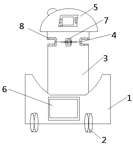
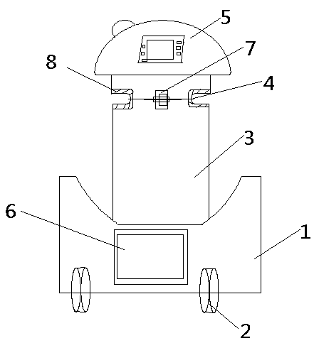
[0035] Such as figure 1 A pay-off device for wire and cable construction shown in the figure includes: base 1, casters 2, wire post 3, wire / cable 4, limit device 5 and control device 6, the control device 6 Equipped with input mechanism, drive mechanism, alarm device, power supply device and control mechanism;
[0036] The relationship between the above components is as follows:
[0037] The caster 2 is arranged under the base 1, the upright column 3 is arranged on the base 1 in a forward-inclined shape, the wire / cable 4 release end is arranged on the line post 3, and the position limiting Device 5 is arranged on the top of line post 3, and described control device 6 is arranged on base 1; Described input mechanism is provided with input device, and described drive mechanism is provided with caster drive device, and described alarm device Set on the limit device 5, the input mechanism, drive mechanism and alarm device are all connected to the power supply device, and the inp...
Embodiment 2
[0043] A pay-off device used in the wire and cable construction process described in this embodiment has the same structure as that in Embodiment 1.
[0044] Such as figure 1 A pay-off device for wire and cable construction shown in the figure includes: base 1, casters 2, wire post 3, wire / cable 4, limit device 5 and control device 6, the control device 6 Equipped with input mechanism, drive mechanism, alarm device, power supply device and control mechanism;
[0045] The relationship between the above components is as follows:
[0046] The caster 2 is arranged under the base 1, the upright column 3 is arranged on the base 1 in a forward-inclined shape, the wire / cable 4 release end is arranged on the line post 3, and the position limiting Device 5 is arranged on the top of line post 3, and described control device 6 is arranged on base 1; Described input mechanism is provided with input device, and described drive mechanism is provided with caster drive device, and described ...
PUM
 Abstract
Description
Claims
Application Information
 - R&D
- Intellectual Property
- Life Sciences
- Materials
- Tech Scout
- Unparalleled Data Quality
- Higher Quality Content
- 60% Fewer Hallucinations
Browse by: Latest US Patents, China's latest patents, Technical Efficacy Thesaurus, Application Domain, Technology Topic, Popular Technical Reports.
© 2025 PatSnap. All rights reserved.Legal|Privacy policy|Modern Slavery Act Transparency Statement|Sitemap|About US| Contact US: help@patsnap.com


