
Bucket Mounted Multi-Stage Turbine Interstage Seal and Method of Assembly

An interstage sealing, turbine stage technology, applied in blade support elements, engine elements, machines/engines, etc., to solve problems such as high cost

Active Publication Date: 2016-10-26
GENERAL ELECTRIC TECH GMBH
View PDF3 Cites 0 Cited by
  • Summary
  • Abstract
  • Description
  • Claims
  • Application Information

AI Technical Summary

Problems solved by technology

However, this does not isolate the turbine rotor wheel from the hot gas path, thus requiring costly higher performance alloys for the rotor section to withstand the severe temperatures in a hot gas intake event

Method used


Image

  • Bucket Mounted Multi-Stage Turbine Interstage Seal and Method of Assembly
  • Bucket Mounted Multi-Stage Turbine Interstage Seal and Method of Assembly
  • Bucket Mounted Multi-Stage Turbine Interstage Seal and Method of Assembly

Examples


Embodiment Construction

[0171] When introducing elements of various embodiments of the present disclosure, the articles "a," "an," "the," and "said" mean that there are one or more of the elements. The terms "comprising," "including," and "having" are intended to be inclusive and mean that there may be additional elements other than the listed elements. Any examples of operating parameters are not exclusive of other parameters of the disclosed embodiments. Also, as used herein, an "axial" direction is a direction parallel to the central axis, and a "radial" direction is a direction extending from and perpendicular to the central axis. An "outer" position refers to a position in the radial direction that is further from the central axis than an "inner" position.

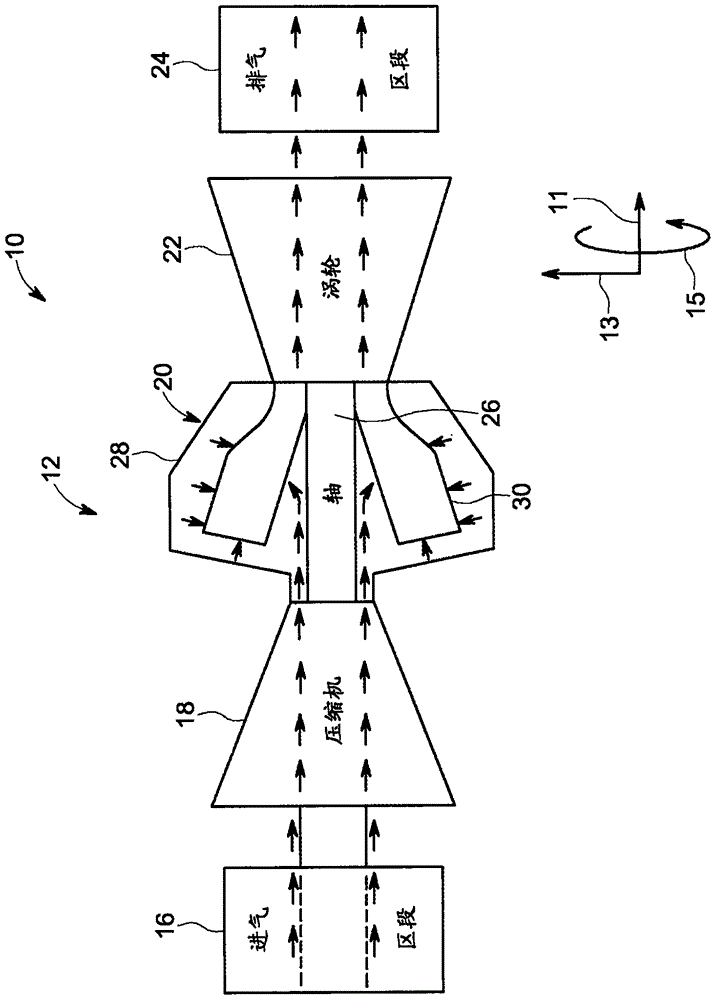
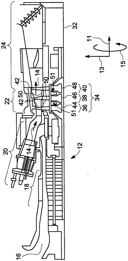
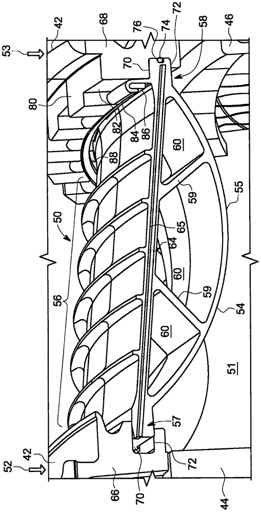
[0172] figure 1 is a block diagram of an exemplary system 10 including a multi-stage turbine engine 12 that may employ the interstage seals described in detail below. In some embodiments, system 10 may include an aircraft, ship, locomotiv...


PUM


Abstract

A sealing system for a multi-stage turbine includes multiple interstage seal segments disposed circumferentially about a turbine rotor wheel assembly and extending axially between a forward turbine stage and an aft turbine stage. Each of the interstage seal segments includes a forward end portion including an outer seal surface and an inner support face, an aft end portion, including an outer seal surface and an inner support face and a main body portion extending axially from the forward end portion to the aft end. The main body portion includes at least two support webs coupling the outer seal surfaces and the inner support faces. The outer seal surfaces are configured to be retained in a radial direction by a land support on each of a forward and aft stage turbine buckets, such that substantially all the centrifugal load from the multiple interstage seal segments is transferred to the forward and aft stage turbine buckets. A method of assembling the sealing system is disclosed.

Description

technical field [0001] The present application relates generally to multi-stage turbines and, more particularly, to interstage seals within multi-stage turbines. Background technique [0002] Generally, turbine engines combust a mixture of compressed air and fuel to produce hot combustion gases. Combustion gases may flow through one or more turbine stages to generate power for loads and / or compressors. Pressure drops may occur between stages, which may allow leakage flow of fluids, such as combustion gases, through unintended paths. It is desirable to confine the combustion gases within a defined annular flow path, to shield certain rotor sections and to maximize power extraction. Furthermore, the turbine rotor wheels supporting the blades (buckets) experience significant thermal loads during their operational life and therefore need to be cooled. Accordingly, seals, eg, mechanical seals, may be disposed between stages to reduce fluid leakage between stages and also preve...

Claims


Application Information

Patent Timeline
Patent Type & Authority Applications(China)
IPC IPC(8): F01D11/00
CPCF01D11/003F01D5/06F01D5/3007F01D11/001F01D11/005F01D11/006F01D11/02F05D2230/60F01D5/12F05D2220/30F05D2240/24F05D2240/55F05D2260/97
Inventor O·萨穆拉拉F·J·卡萨诺瓦E·塞文瑟J·M·维布斯特
Owner GENERAL ELECTRIC TECH GMBH
Features
  • Generate Ideas
  • Intellectual Property
  • Life Sciences
  • Materials
  • Tech Scout
  • Unparalleled Data Quality
  • Higher Quality Content
  • 60% Fewer Hallucinations
Learn More