Supercharge Your Innovation With Domain-Expert AI Agents!

A thin-walled crossed roller bearing assembly process

A technology of cross roller bearings and assembly technology, which is applied in the direction of shafts and bearings, bearing components, mechanical equipment, etc., can solve the problems of inability to accurately repeat the positioning of assembly cylinders, poor assembly repeat positioning accuracy, and affect product performance and product life. Achieve the effect of improving the inaccurate repeated positioning, improving product quality and life, and improving the repeated positioning accuracy

Active Publication Date: 2020-03-24
苏州普拉米精密机械有限公司
View PDF8 Cites 0 Cited by
  • Summary
  • Abstract
  • Description
  • Claims
  • Application Information

AI Technical Summary

Problems solved by technology

[0003] In the existing technology, the existing assembly shortcomings or shortcomings are: 1. The assembly cylinder cannot be accurately and repeatedly positioned, resulting in a significant increase in processing accuracy, thereby increasing equipment and manufacturing costs; 3. During processing and production, because the rollers do not run smoothly in the raceway, the defect rate increases; 4. Although the assembly cylinder and the raceway are formed together, when the roller is assembled, the assembly cylinder must be taken out first , after loading the rollers, put the assembly cylinder back in place, the axial error and radial error between the V-shaped groove and the V-shaped raceway under the assembly cylinder cannot be positioned accurately, making the rollers in the groove Unsmooth operation in the road will affect product performance and product life

Method used


Image

  • A thin-walled crossed roller bearing assembly process
  • A thin-walled crossed roller bearing assembly process
  • A thin-walled crossed roller bearing assembly process

Examples


Embodiment Construction

[0034] The following will clearly and completely describe the technical solutions in the embodiments of the present invention with reference to the accompanying drawings in the embodiments of the present invention. Obviously, the described embodiments are only some, not all, embodiments of the present invention. Based on the embodiments of the present invention, all other embodiments obtained by persons of ordinary skill in the art without creative efforts fall within the protection scope of the present invention.

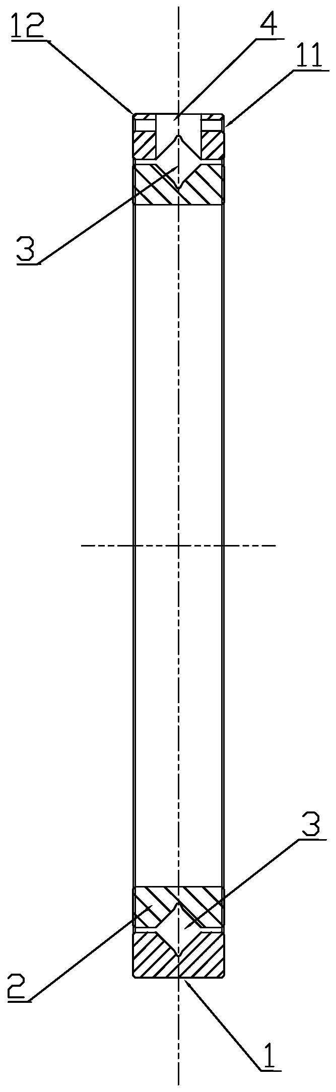
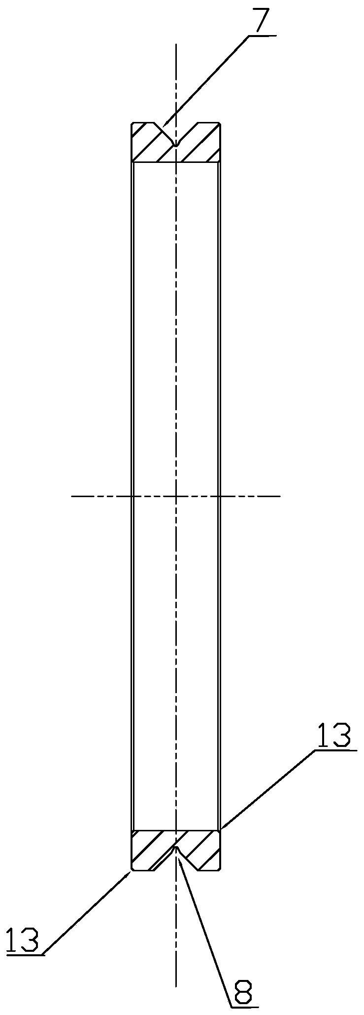
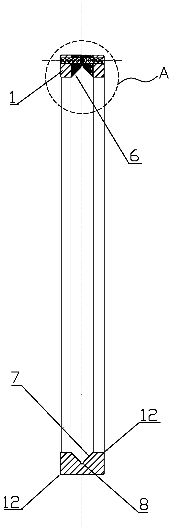
[0035] according to figure 1 , figure 2 , image 3 and Figure 4 , the present invention provides a thin-walled crossed roller bearing, comprising bearing outer ring 1, bearing inner ring 2, roller 3, assembly round hole 4, assembly cylinder 5, V-shaped groove 6, V-shaped raceway 7, V-shaped Type arc groove 8, semi-locating pin 9, guide head 10, pin hole 11, outer ring chamfer 12, inner ring chamfer 13.

[0036] The bearing outer ring 1 is equipped with a bear...


PUM


Abstract

The invention discloses a thin-walled crossed roller bearing. The thin-walled crossed roller bearing comprises a bearing outer ring, a bearing inner ring, a roller, a round assembling hole, an assembling cylinder, a V-shaped groove, V-shaped roller path, a V-shaped arc groove, half positioning pins and pin holes; the bearing inner ring is assembled in the bearing outer ring; the V-shaped roller path is arranged on the inner side of the bearing outer ring and the outer side of the bearing inner ring and is internally provided with the V-shaped arc groove; the round assembling hole is formed in the middle portion of the bearing outer ring and is internally provided with the assembling cylinder; the pin holes are formed in the bearing outer ring side face of the round assembling hole and the bearing outer ring side face of the assembling cylinder; and the two half positioning pins with guiding heads are arranged in the pin holes of the bearing outer ring. According to the thin-walled crossed roller bearing, the two half positioning pins are arranged on the bearing outer ring, the problem that repeated positioning is not accurate is obviously solved through overall grinding and machining forming, the problem that the operation of the V-shaped roller path and the roller is not smooth is thoroughly solved, the product yield is substantially increased, the manufacturing cost is reduced, meanwhile, the product performance is improved, and the service life of the bearing is prolonged.

Description

technical field [0001] The invention relates to the technical equipment field of a thin-walled roller bearing, in particular to an assembly process of a thin-walled crossed roller bearing. Background technique [0002] Precision thin-walled crossed roller bearings are generally divided into two types: split outer ring and integral inner and outer ring. The integral thin-walled crossed roller bearing with inner and outer rings usually has an assembly hole in the middle of the outer diameter surface of the outer ring for loading the rollers. And install the assembly cylinder tightly in the roller assembly hole, set a 1 mm through hole horizontally on the assembly cylinder, and insert a positioning cylindrical pin in the through hole, and position the assembly cylinder through the positioning pin. [0003] In the existing technology, the existing assembly shortcomings or shortcomings are: 1. The assembly cylinder cannot be accurately and repeatedly positioned, resulting in a si...

Claims


Application Information

Patent Timeline
Patent Type & Authority Patents(China)
IPC IPC(8): F16C43/06
CPCF16C43/06
Inventor 顾建祖
Owner 苏州普拉米精密机械有限公司
Features
  • R&D
  • Intellectual Property
  • Life Sciences
  • Materials
  • Tech Scout
  • Unparalleled Data Quality
  • Higher Quality Content
  • 60% Fewer Hallucinations
Learn More