Pot support for cooker

A technology for a pot holder and a cooker, which is applied in the cooker field, can solve the problems of easy failure of adhesive, soiled panels, peeling off of rubber pads, etc., and achieves the effects of avoiding excessive heating and aging, prolonging service life and facilitating assembly.

Inactive Publication Date: 2016-10-26
NINGBO FOTILE KITCHEN WARE CO LTD
View PDF8 Cites 1 Cited by
  • Summary
  • Abstract
  • Description
  • Claims
  • Application Information

AI Technical Summary

Problems solved by technology

[0003] However, due to the heating of the pot support during the cooking process, the temperature is high, the glue is easy to fail, and the rubber pad falls off from the pot support; or the adhesiveness is reduced, and the glue pad will be misplaced on the pot support under the action of external force, resulting in unbalanced support ;In addition, the sliding of the rubber pad will stain the panel, making it difficult to clean

Method used


Image

  • Pot support for cooker
  • Pot support for cooker
  • Pot support for cooker

Examples


Embodiment 1

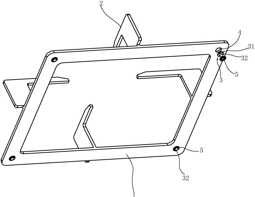
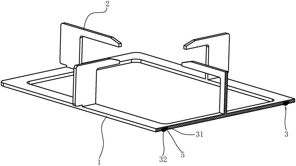
[0034] like Figure 1 to Figure 4 Shown, the cooktop pan support includes:

[0035] The base 1 is the foundation of the entire pot support, and the upper surface of the base 1 is provided with a plurality of legs 2 at intervals; the lower surface of the base is provided with a plurality of blind holes 4 at intervals.

[0036] Feet 3 is a heat-resistant rubber pad, including a support portion 31 and a connection portion 32, the cross section of the support portion 31 is adapted to the cross section of the blind hole 4; the connection portion 32 is connected to the middle part of the support portion 31, and the connection portion 32 The cross-sectional area is smaller than that of the support portion 31 .

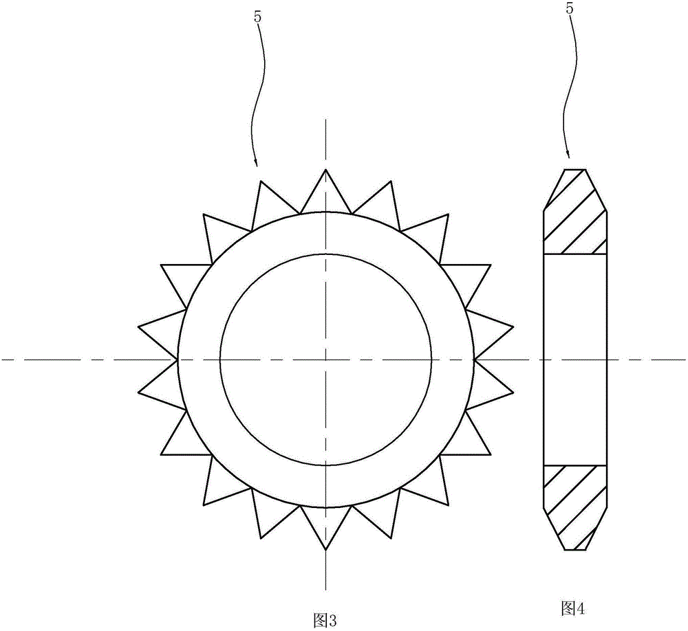
[0037] The positioning part 5 is a ring-shaped structure, and its outer circumference is gear-shaped, which is a metal part that can be deformed under the action of an external force; the cross-section of the through hole in the middle of the positioning part 5 is larger tha...

Embodiment 2

[0040] like Figure 5 to Figure 7 As shown, the pan support for the cooker has a blind hole 4 on the lower surface of the base 1, and a supporting foot (not shown in the figure) on the upper surface.

[0041] The positioning part 5 is a bendable pin structure, made of metal material; one end of the positioning part 5 is welded on the lower surface of the base 1 .

[0042] The footing 3 includes a supporting part 36 and a connecting part 37 connected to each other. The connecting part 37 is inserted in the blind hole 4. The supporting part 36 is exposed to the blind hole 4 and is blocked on the lower surface of the base 1. The supporting part 36 is close to the connecting part. 37 is provided with a transverse shaft hole 34 .

[0043] The other end of the positioning member 5 is passed through the shaft hole 34 so as to lock the pad 3 in the blind hole 4 .

Embodiment 3

[0045] like Figure 8 to Figure 10 As shown, the pan support for the cooker has a blind hole 4 on the lower surface of the base 1, and a supporting foot (not shown in the figure) on the upper surface.

[0046] The positioning piece 5 is arranged in the blind hole 4 and is an interference fit with the blind hole 4 .

[0047] The positioning member 5 is provided with a stepped hole 51 with a large top and a small bottom.

[0048] The pad 3 includes a supporting part 31, a connecting part 32 and a card seat 33; the connecting part 32 is connected between the supporting part 31 and the card seat 33; On the step 54, the connecting part 32 is accommodated in the small hole 53 of the stepped hole 51, and the support part 31 is blocked outside the stepped hole 51 and against the lower surface of the base; the positioning part 5 is arranged in the blind hole 3 and It is an interference fit with the blind hole 3.


PUM


Abstract

The invention relates to a pot support for a cooker. The pot support comprises a base. Foot pads are arranged on the lower surface of the base. The pot support is characterized in that blind holes are formed in the lower surface of the base, the foot pads are contained in the blind holes, and locating parts used for locating the foot pads are arranged in the blind holes. Preferably, each locating part is of a ring structure and is in interference fit with the corresponding blind hole. Metal parts are adopted as the locating parts. Compared with the prior art, the blind holes are formed in the lower surface of the base of the pot support for the cooker, the locating parts are adopted for limiting the foot pads into the blind holes, and the foot pads are located firmly, do not slide due to external force, and support balance of the base and a pot on the foot pads. In the preferable scheme, the deformable metal parts are adopted as the locating parts, assembling is convenient and labor-saving, heat can be transferred to the base, the situation that the foot pads are aged due to excessive heating is avoided, and the service life of the foot pads is prolonged.

Description

technical field [0001] The invention relates to the field of cooking utensils, in particular to a pan support for a cooking utensil. Background technique [0002] The existing pot support for cooker usually includes a ring-shaped base seated on the cooker panel, and a plurality of pads are arranged at intervals on the lower surface of the base. In order to avoid the pot support from scratching the cooker panel, the feet usually adopt rubber pads, which are bonded to the lower surface of the pot support by glue. [0003] However, due to the heating of the pot support during the cooking process, the temperature is high, the glue is easy to fail, and the rubber pad falls off from the pot support; or the adhesiveness is reduced, and the glue pad will be misplaced on the pot support under the action of external force, resulting in unbalanced support ;In addition, the sliding of the rubber pad will make the panel dirty and difficult to clean. Contents of the invention [0004]...

Claims


Application Information

Patent Timeline
Patent Type & Authority Applications(China)
IPC IPC(8): F24C15/08
CPCF24C15/08
Inventor 王帅东茅忠群诸永定郑军妹
Owner NINGBO FOTILE KITCHEN WARE CO LTD
Why Eureka
Try Eureka