Detachable turbine air purifier

An air purifier and detachable technology, which is applied in the field of detachable turbine air purifiers, can solve the problems of a single circulation circuit of the air purifier, difficulty in improving the purification performance of the air purifier, and prolonging the time for absorbing unclean gas, etc. To achieve the effect of easy internal cleaning, easy timed replacement, and improved air circulation speed

Inactive Publication Date: 2016-10-26
ZHEJIANG SCI-TECH UNIV
View PDF17 Cites 12 Cited by
  • Summary
  • Abstract
  • Description
  • Claims
  • Application Information

AI Technical Summary

Problems solved by technology

[0002] The air circulation of traditional air purifiers is mostly realized by axial flow fans or centrifugal fans. Generally, only a single axial flow fan or centrifugal fan is configured, so the circulation loop inside the air purifier is single.
This structure is difficult to improve the purification performance of the air purifier, and cannot completely purify the air in a limited space in a short time, which not only prolongs the time for the human body to absorb unclean gas, aggravates the harm to the human body, but also increases the energy consumption. consume

Method used


Image

  • Detachable turbine air purifier
  • Detachable turbine air purifier
  • Detachable turbine air purifier

Examples


Embodiment Construction

[0026] The present invention will be further described below in conjunction with the accompanying drawings, but the present invention is not limited to the following examples.

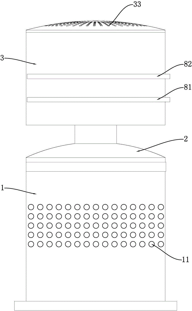
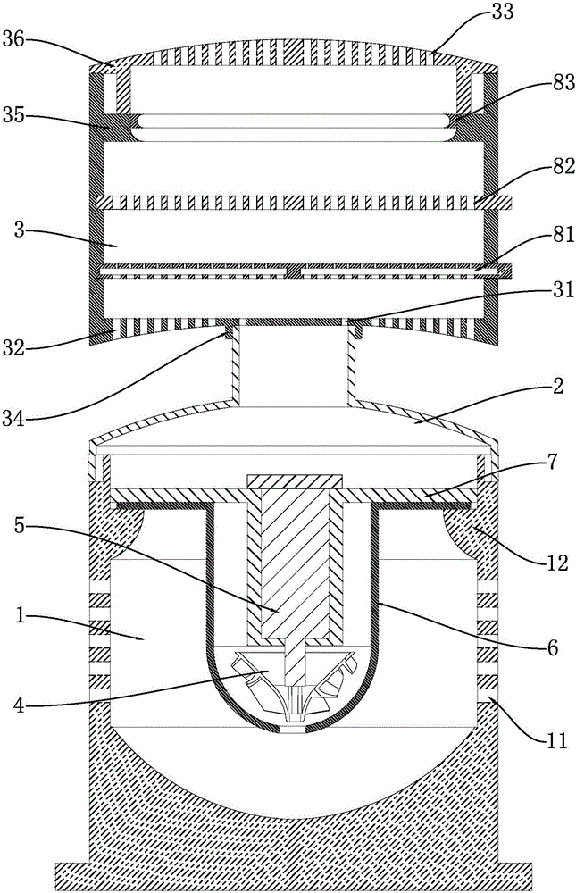
[0027] Such as figure 1 As shown, a detachable turbo air cleaner includes an air intake chamber at the bottom and a purification chamber arranged above the air intake chamber.

[0028] The air intake chamber includes a lower shell 1, a connection cover 2 mounted on the top of the lower shell, and an air intake mechanism arranged in the inner cavity of the lower shell.

[0029] The top of the lower casing is open, the side wall of the lower casing is provided with several primary air inlet holes 11, and the bottom surface of the inner cavity of the lower casing is an arc-shaped concave surface. The connecting cover is installed on the top of the lower housing; the bottom of the connecting cover is an air inlet 21 connected to the top opening of the lower housing, and the top of the connecting cover is ...


PUM


Abstract

The invention relates to a detachable turbine air purifier. According to the purpose, the detachable turbine air purifier should have the beneficial effects of being high in purifying efficiency and low in energy consumption. According to the technical scheme, the detachable turbine air purifier comprises an air inlet chamber and a purifying chamber. The air inlet chamber comprises a lower shell, a connecting cover arranged on the top of the lower shell and connected with the purifying chamber, and an air inlet mechanism arranged in an inner cavity of the lower shell and used for feeding air into the purifying chamber. The top of the lower shell is provided with an opening, and multiple first-level air inlet holes are formed in the side wall of the lower shell. The cross section of the connecting cover is gradually reduced from bottom to top. An air inlet in the bottom of the connecting cover is in butt joint with the opening in the top of the lower shell, and an air outlet in the top of the connecting cover is in butt joint with a bottom plate of an upper shell. The purifying chamber comprises the upper shell and a purifying assembly arranged in an inner cavity of the upper shell and used for cleaning air; a top plate of the upper shell is provided with air outlet holes; and jet flow holes communicating with an inner cavity of the connecting cover and multiple second-level air inlet holes formed in the peripheries of the jet flow holes are formed in the bottom plate of the upper shell.

Description

technical field [0001] The invention relates to the field of air cleaners, in particular to a detachable turbo air cleaner. Background technique [0002] The air circulation of traditional air purifiers is mostly realized by axial flow fans or centrifugal fans. Generally, only a single axial flow fan or centrifugal fan is configured, so the circulation loop inside the air purifier is single. This structure is difficult to improve the purification performance of the air purifier, and cannot completely purify the air in a limited space in a short time, which not only prolongs the time for the human body to absorb unclean gas, aggravates the harm to the human body, but also increases the energy consumption. consume. Therefore, based on the above description, there is an urgent need to design a purifier with a higher air circulation rate to improve the efficiency of purifying air. Contents of the invention [0003] The purpose of the present invention is to overcome the shor...

Claims


Application Information

Patent Timeline
Patent Type & Authority Applications(China)
IPC IPC(8): F24F1/02F24F13/20F24F13/00F24F13/28F04D25/08F04D29/42B01D46/10B01D46/30B01D53/02
CPCB01D46/10B01D46/30B01D53/02F04D25/08F04D29/4206F24F1/02F24F13/00F24F13/20F24F13/28B01D2253/102B01D2258/06B01D2267/40B01D46/62
Inventor 金英子毛弘亚向新贤
Owner ZHEJIANG SCI-TECH UNIV
Why Eureka
Try Eureka